an alternative eap fabrication tutorial
This project was part of a Masters of Architecture design studio in Digital Architecture from the University of Sydney, Australia. After becoming interested in Electroactive Polymers and their potential as a performative installation we came upon the Materiability Research Network. From tutorials and videos posted on this site we attempted to fabricate our own EAP. This process took place over 4 months at the end of 2012.
Materials and Tools
|
|
1. Fabrication of stretching mechanism
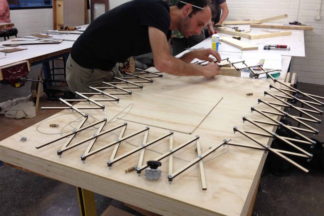
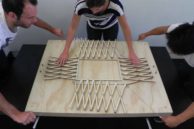
Design Scissor Stretcher frame – you must allow the sizing of the frame to stretch the Structural Tape to 300% of its original size. The frame works best when it is designed as a square, however if your sheets are not square then it will be more efficient to design your stretcher as a rectangle. Laser cut elements and assemble – pin at joints with bolts or pop rivets (joints must be strong but allow smooth movement of joint). Attach cable/cord to four corners to pull outwards frame with. This can be done by looping and crimping the cable in place .It is important that the points along the inside edge of the stretching frame have as large a surface area as possible. The structural tape will adhere to the frame at these points and will remain in place best if it is stretched over a lip (ie. a bolt head).
2. Laser cutting plywood and polycarbonate frames
Design polycarbonate frames. This process requires many iterations to perfect. As a rule of thumb the shape will always deform along the shorter axis. The best results were achieved with a square shape which was slightly longer along one diagonal axis than the other. Laser cut frames ensuring maximum ventilation possible. Design Plywood frames – ensure that you leave a minimum 20mm buffer between the inside of the plywood frame and the outside of the polycarbonate frame. This benefits the fabrication process. Ensure the design includes rounded corners on the outside of the plywood frame so that it will not rip the Structural tape. Polycarbonate is an inconsistent material – each sheet may have different material properties and therefore can perform differently. Check with your laser cutting technician before you cut this plastic. Alternatively you can use clear polypropylene for the frame, however you must ensure it is a clear surface.
3. Stretching structural tape
Cut the desired size of structural tape required. To cut the tape lay down black rubber on a bench top – the tape can be easily removed from the rubber and therefore will not stick. Ensure you wipe the rubber with methylated spirits before laying the tape down to remove any impurities. Cut extra 10mm strips of structural tape to reinforce the edges of the sheet. Clean the contact points of the stretching mechanism with methylated spirits to remove any dust. Remove the red plastic seal from the back of the structural tape and adhere edges to stretching mechanism – do not discard this plastic sheet as it is used in the next stage of fabrication. Tape down each point where there structural tape adheres to the stretching mechanism with domestic scotch tape. Stretch out the frame, pulling the cables connected the each corner until the tape is at 300% of its original size. This must be done slowly to allow the material to adjust and evenly to ensure the material is stretched uniformly. Stretch the tape out until you are able to slip the plywood pre-stretch frame underneath the stretching mechanism and adhere to the under -inside edges of the structural tape. Reinforce the edges of the pre-stretch frame (on top of the structural tape) with strips of duct tape. Carefully detach the structural tape from the scissor stretching mechanism by wrapping the structural tape around with edges of the pre-stretch frame. This process requires a minimum of 4 people to carry out – 2 people pulling the cables out, 1 person ensuring the structural tape does not come away from the frame and 1 person to slip the plywood-prestretch frame underneath. If the ambient room temperature is above 20°C, put the structural tape into a refrigerator for 10mins before stretching it. If the tape it too warm it will fail and tear easily.
4. Applying carbon graphite powder to structural tape
Laydown black rubber on work surface and clean with methylated spirits. Clean the polycarbonate with methylated spirits, then adhere it to the structural tape which has been stretched over the plywood frame. Ensuring the black rubber is under the pre-stretch plywood frame, firmly press your finger along the polycarbonate frame to remove any air bubbles. Cut the red plastic seal (which was removed from the structural tape in stage 3) into 10mm strips. Adhere these along the inside edge of the polycarbonate frame to the structural tape – these create a border inside the polycarbonate frame. Do this on both sides of the structural tape. Liberally apply carbon graphite powder on the inside of the red plastic seal strips to the structural tape. This can be done with a paint brush or fingers. Do this on both sides of the structural tape. Remove red plastic seal strips. Remove the module from the plywood pre-stretch frame by using a stanley knife and scissors to cut the structural tape around the outer edge of the polycarbonate frame. The structural tape should naturally rip along the edge of the frame. Be careful not the allow any carbon graphite powder on the edge of the polycarbonate frame – this can comprise the performance of the module. It is important to apply as much carbon graphite as possible to the structural tape in an even manner to achieve maximum conduction.
5. Connection to power converter
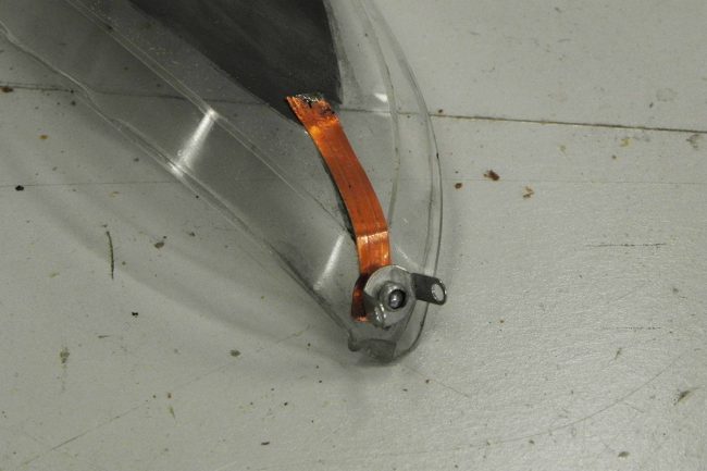
Cut two 100mm strips of copper tape. Scratch off 20mm of the plastic covering from each end on both sides of the tape. Apply flux and solder to the ends of the tape to create a smooth connection – if there are imperfections in the soldered surface the module will fail once voltage is applied. Adhere 1 piece of copper tape to the corner of the module, allowing it to hang 50mm over the edge of the polycarbonate frame. Fix it in place with domestic scotch tape – ensure it is firmly touching the carbon graphite powder. Adhere the other piece of copper tape in the same way to the opposite corner and side of the module. Connect electrodes with alligator clips to the end of each copper tape. Connect the power converter to electrodes (positive on one and negative on the other). Oscillate between 0V and 7000V. Extreme care must be taken at this stage – if you are inexperienced with high voltage electricity do not attempt this stage without first seeking advice from an expert. High voltage electricity can be extremely dangerous and unstable. Also take care to ensure that the soldered surface is free from any sharp edges – these create weaknesses in the structural tape which causes the voltage to ‘arc over’ ie. form a current and cut out/fail. It is also important that there is a minimum 3mm buffer between the inside edge of the polycarbonate frame and the start of the carbon graphite powder for the same reason.
The greatest deformations can be achieved when the stress between the polycarbonate frame and structural tape is almost equal. When voltage is passed through the module it only weakens the structural tape minimally; therefore if the polycarbonate frame is not closely matched in strength to the structural tape there will not be a great amount of displacement.


