USB Connector
Overview

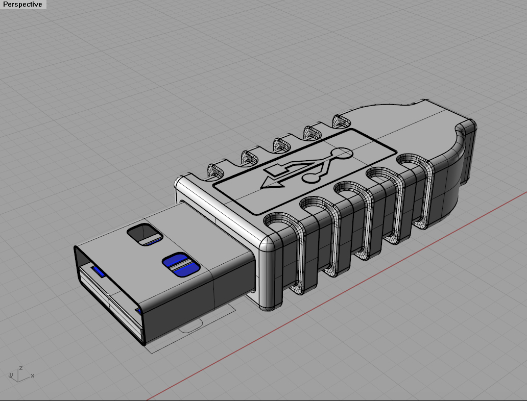
In this tutorial, you will learn how to model a USB connector using the tools you learned before as well as new commands. You will learn how to use a reference image to help you model a 3D object in detail. 

Step One

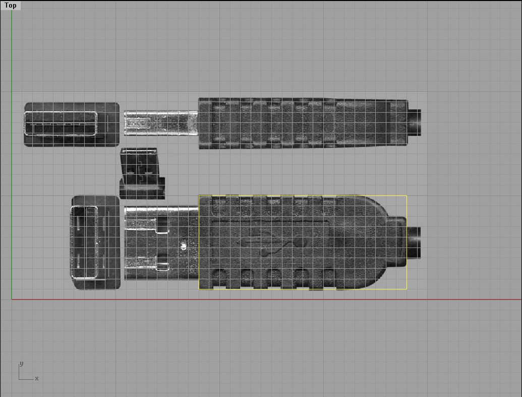
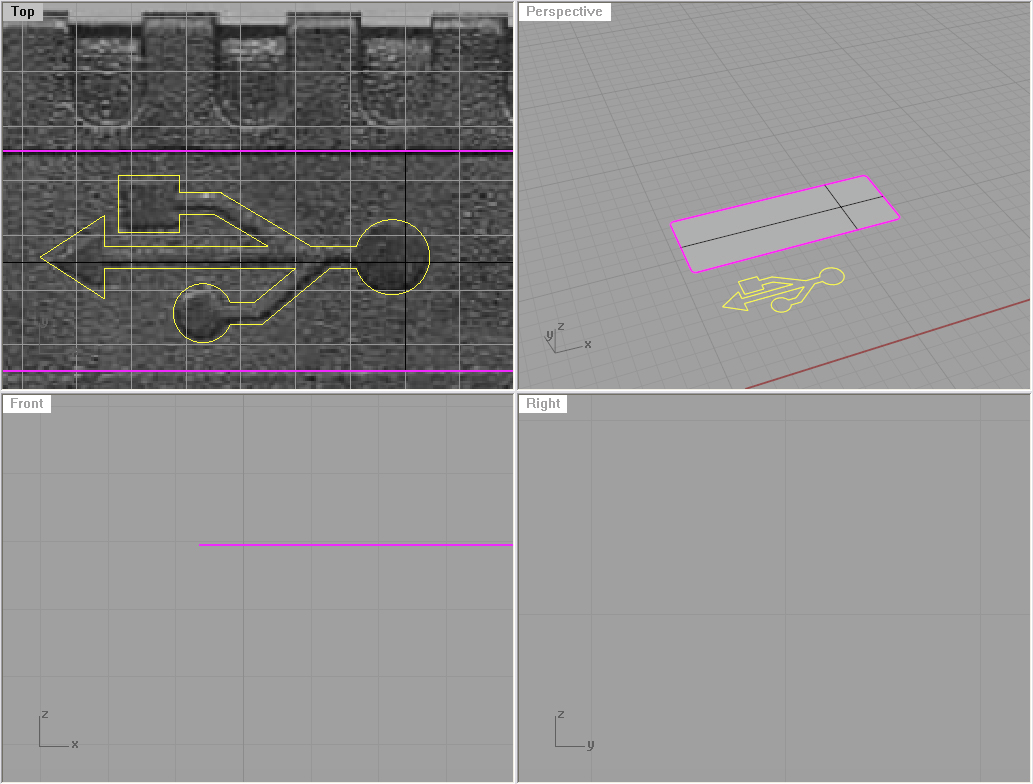
To begin with, we need a reference image which will help us model this USB connector. So, please use this one, and position it on the background of the Top viewport using Picture Frame or Background Bitmap. Make it 40 units in width (make sure you’ve got your Snap turned on).

Then using the Rectangle command create one rectangle like on the image (please note, if you followed the above instructions, then you will have no problems aligning the rectangle according to the image.

Instructions
Nadia Elkady

Duration
120 min

Level
Advanced

→ DOWNLOAD PDF


Explode that rectangle into 4 lines with the Explode command, and then Offset the upper and lower ones by 2 units inwards. Now, create an Arc using the Mid Osnap option  and position it like on the image. You will have to turn off the snap option, and turn on the Ortho for moving the arc straight. After that trim off the lines you don’t need with the Trim command.

Join all the curves and lines, and extrude them with the ExtrudeCrv command (make sure you have the Cap option set to yes). The extrusion distance is 5 units.

Now, Offset the joint curve by 0.5 units, and move that offset curve upwards (from Front or Right viewport) by 0.5 units, and Extrude it by 4 units.

Using the FilletEdge command, set the fillet radius to 0.4 units, and fillet all edges (of both outer and inner objects).

Now, using the Rectangle command (make sure you click on Rounded in Rectangle options before setting first corner) create a rounded rectangle in the Top viewport and position it like on the image below:

Copy it 5 times, and Mirror those 5 so you get something like on the first image on the left.

Using the Project command, project those curves on both objects from the Top viewport.

Hint: Always project curves from the viewport in which you initially drew them.  

Trim the upper surface with the upper curves and the inner surface with the inner curves.

Now, isolate two curves like on the image. We will create a surface between them.

Using the End Osnap and Perp Osnap we will create cross section lines. The curves are made out of lines and arcs. Using the Curve command with your End Osnap activated, will show you the ends of these lines and arcs. By clicking on the end and moving to the other curve, you will create cross section lines. 

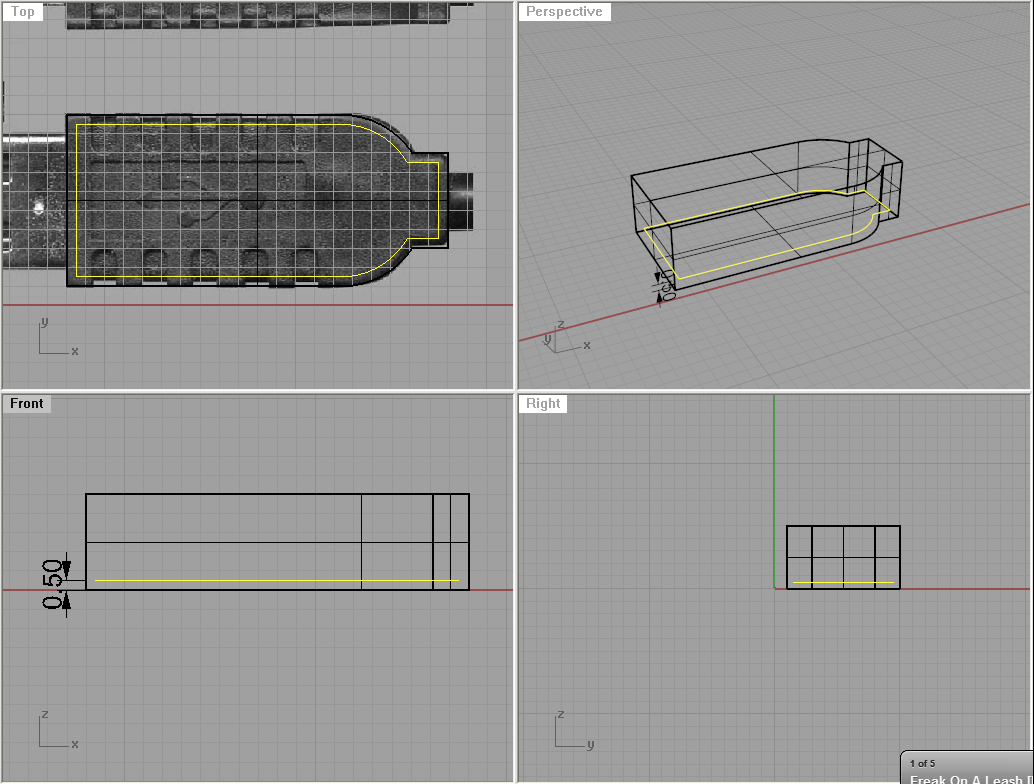
Now, using Sweep2 create a surface using the two curves as rails, and the other lines as cross sections. (Hint: Make sure to select “closed sweep” when the Sweep2 dialogue window appears.) We now need to fill the gaps, so Copy the surface across, then Mirror the 5 copied surfaces to fill the gaps on the other side as well. (Hint: The surfaces have to align perfectly for them to join to the body correctly.)

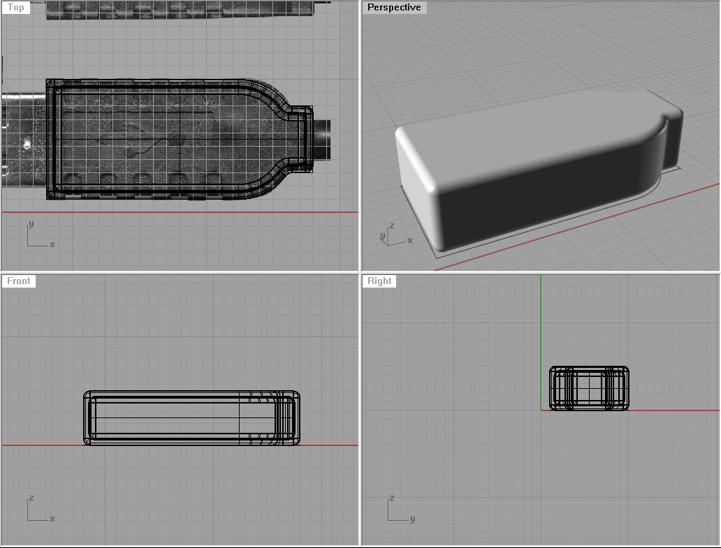
Join all the surfaces, and using the FilletEdge command fillet the new edges (do not worry, you can select everything with your bounding box, as there is no other edge that can be filleted except the ones we need). Use 0.05 units as fillet radius. Note: If the fillet command does not work, that means the surfaces you copied and mirrored did not align perfectly with the body of your USB connector. Hint: Use the ShowEdges command to check if there are any naked edges. Naked edges are areas where your object is open.

Step Two

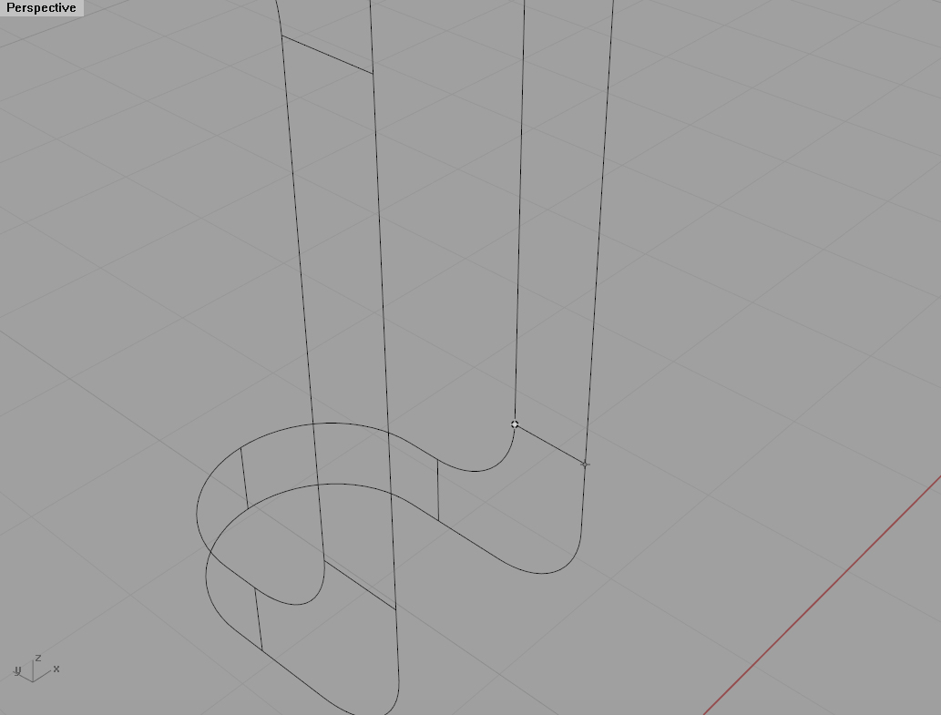
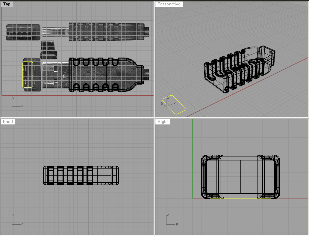
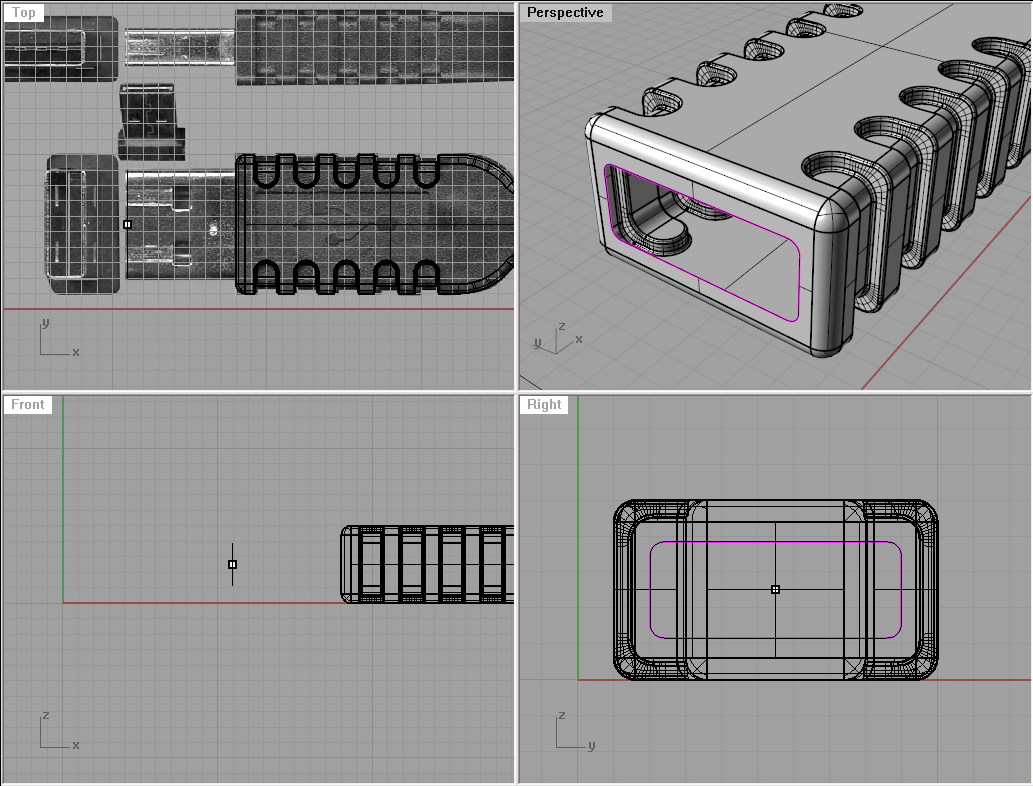
Now we will build the connector itself. So, create a Rectangle with the Rounded option selected, and use the background image as a reference.

Now, rotate and position it the way we need it. Please note, I first created a dot on the intersection of two mids of the two edges of the main body, then moved that dot so it fits the start on the background image. Then with the move tool, and again SmartTrack I found the center of the rounded rectangle, and moved it to that dot. That way I know my rounded rectangle is positioned in the centre of the USB’s body.

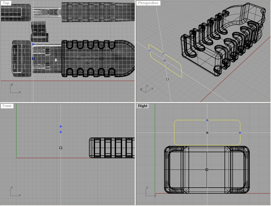
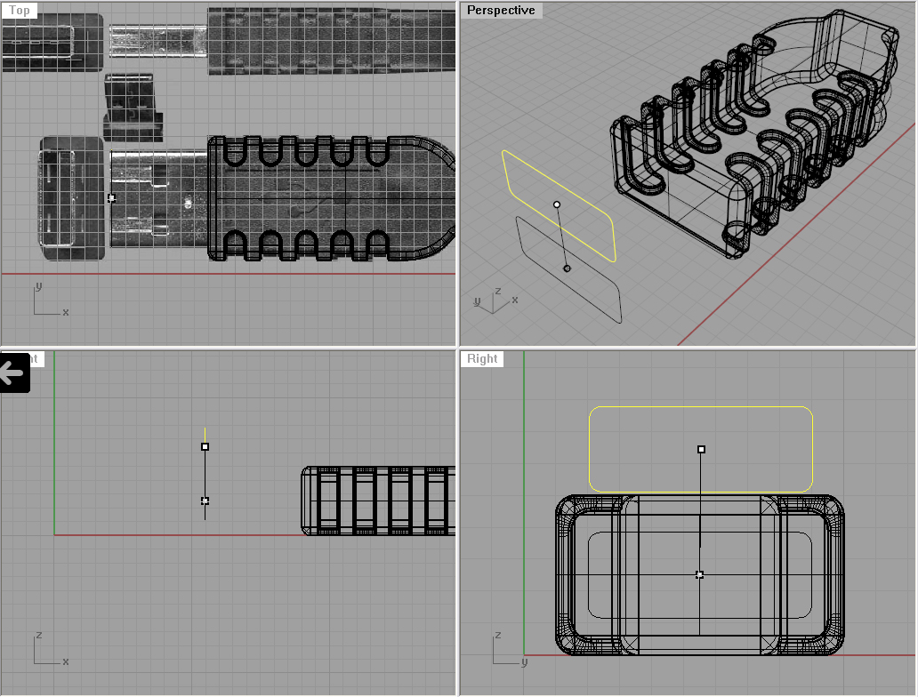
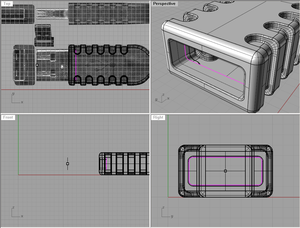
From the Right viewport, Project that rounded rectangle onto the USB body and delete the curves you don’t need. It is the one in the back.

Using trim (or split then delete the inner surface) we will make a hole in the body. Then, we will extrude (either the curve or edge) to the inside a bit (Cap set to no). You can fillet that edge with filletedge command and 0.1 units as the fillet radius. (Prior to that you need to join your newly created surface and the body) 

Extrude the first rounded rectangle, and make it long like the extruded surface make sure you’ve got Cap set to yes.

Offset the rounded rectangle curve by 0.1 towards the inside and trim the surface with it.

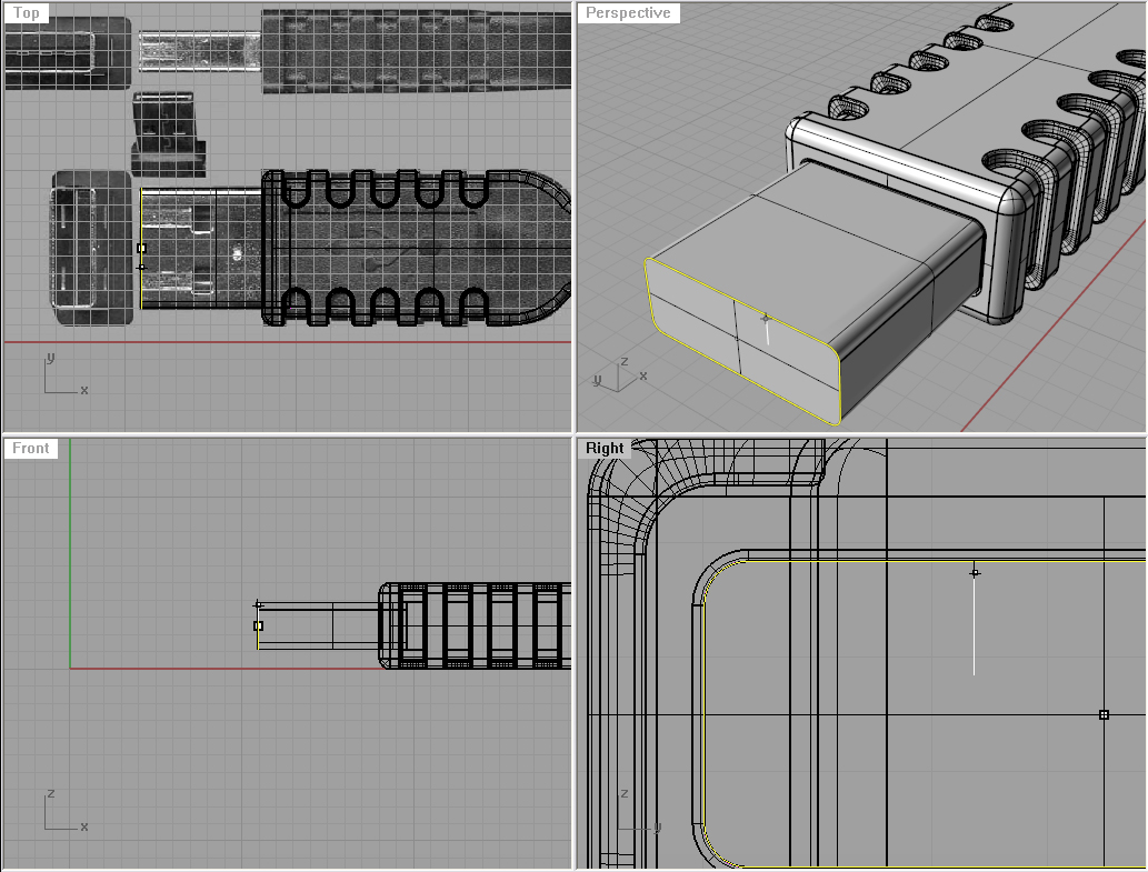
Extrude the inner edge and make it long like the outer surface is. And join all that together so we can use FilletEdge to smooth out the edges. We will use 0.04 units as the fillet radius.

Now, lets make those little holes. We need another rounded rectangle, and position it like on the image. Then you can mirror it and project it onto the connector surface.

Trim the inside parts of the surface, and connect them with Loft. Then you can fillet the edges using 0.04 as the fillet radius.

Lets get back to that first rounded rectangle, and offset it by 0.1 units inwards. Then using the BoundingBox command (world), we will get a rectangle that does not have rounded corners. 

Now we need that newly created rectangle to be a bit smaller. So, we will turn on our control points with PointsOn command, and move the upper two dots down a bit (from the Right viewport). After that just extrude it with Cap set to yes:

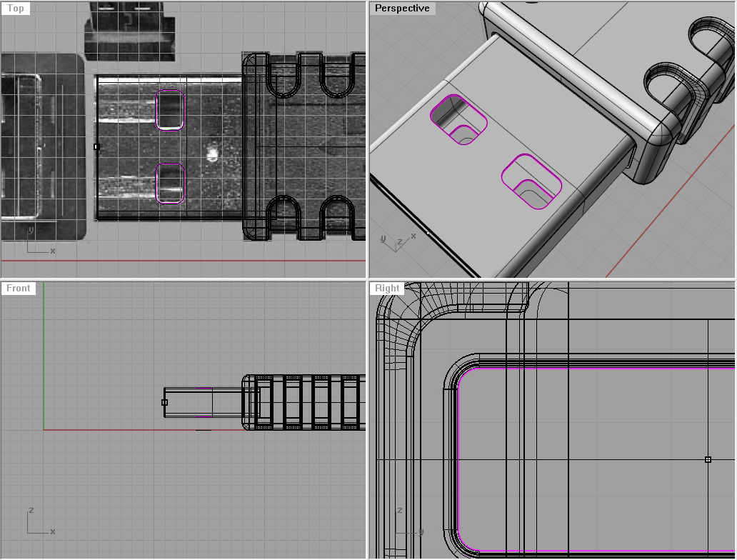
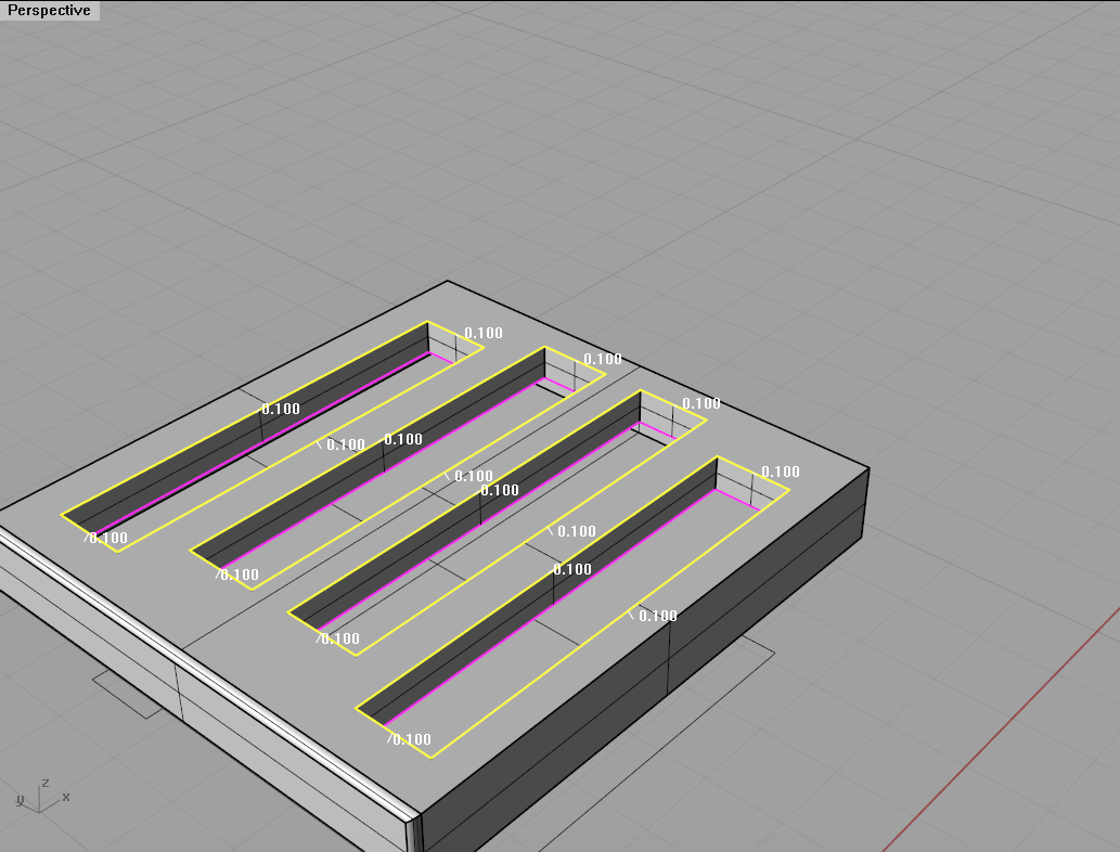
Fillet the visible edges. With the filletedge command and 0.1 units as fillet radius fillet these edges. Hide everything you don’t need and leave only the front object visible. Create 4 rectangles like on the third image below, and move two to the right just a little a bit. Project those rectangles onto the surface, and delete the lower 4 then using the 4 upper ones, split the surface.

Using the extrudecrv command, extrude the projected rectangles down a bit, and copy the extruded rectangles into your clipboard using ctrl+c. We will need those again soon.

Move the 4 little surfaces into the blue layer for easy manipulation. Join those extruded rectangles with your object, and using the filletedge command with 0.1 units as your fillet radius fillet those edges. 

Note: Only the edges that are indicated on the image.

Now, using ctrl+v we will paste another 4 extruded rectangles. We will put them into the blue layer and hide all other layers and show just the blue.

Again, with the filletedge command and 0.1 units as your fillet radius, fillet the edges which are yellow on the image. When you show the parts you had previously hidden, you should end up with the third image on the left.

Step Three

Now, lets make a USB logo on the body. First make a rounded rectangle like on the image, and offset it to the inside by 0.1 units like on the second image below. Project those two rectangles onto the object, and delete all of them, except the two on the upper surface.

Use trim to create what can be seen on the first image left. You will need to move the inner surface down by 0.05 units. Do this from the front or right viewports. Then, using Blendsrf command, blend the two surfaces:

Now, you can explode the whole object, and isolate just one surface like on the image below. Use lines and curves to trace the USB icon.

You need to project that icon onto the surface, then using the split command, split the surface with the icon curves. Move the icon surface up by 0.05 units. Using extrudecrv, extrude the projected icon curves up by 0.05 units.

Now, we will fillet the edges with the filletedge command and 0.04 units as the fillet radius.

And that’s it! You modeled yourself a USB connector. 

Instructions
Nadia Elkady

Duration
Several days

Level
Advanced


Privacy Settings
We use cookies to enhance your experience while using our website. If you are using our Services via a browser you can restrict, block or remove cookies through your web browser settings. We also use content and scripts from third parties that may use tracking technologies. You can selectively provide your consent below to allow such third party embeds. For complete information about the cookies we use, data we collect and how we process them, please check our Privacy Policy
Youtube
Consent to display content from - Youtube
Vimeo
Consent to display content from - Vimeo
Google Maps
Consent to display content from - Google

info(at)materiability.com