Overview
This tutorial demonstrates how to design a 3D model of a Platonic solid—such as a dodecahedron or icosahedron—using Rhino 3D. You will learn how to construct the solid from a base polygon, rotate and join the faces into a closed 3D geometry, and finally unroll the model into a 2D cutting plan suitable for laser cutting or other fabrication methods.
Start a New File
1. Open Rhino.
2. Select File > New and choose the Small Objects – Millimeters template.
• This is ideal for laser cutting or scale modeling.
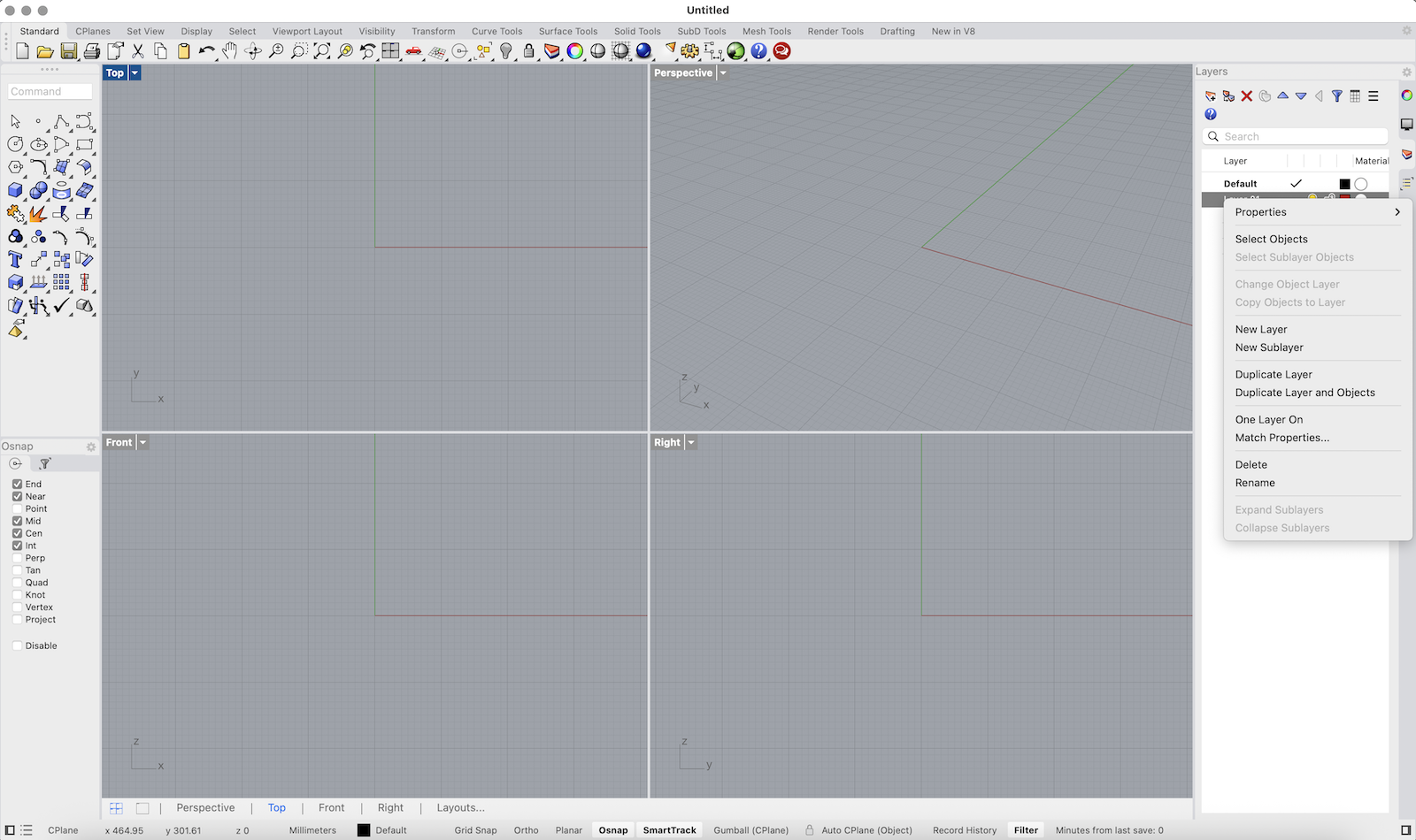
Organize Your Layers
1. On the right side, locate the Layers panel.
2. Right-click on the default layer name (e.g., “Default”) and choose Rename – rename it to Hilfsebene (helper plane).
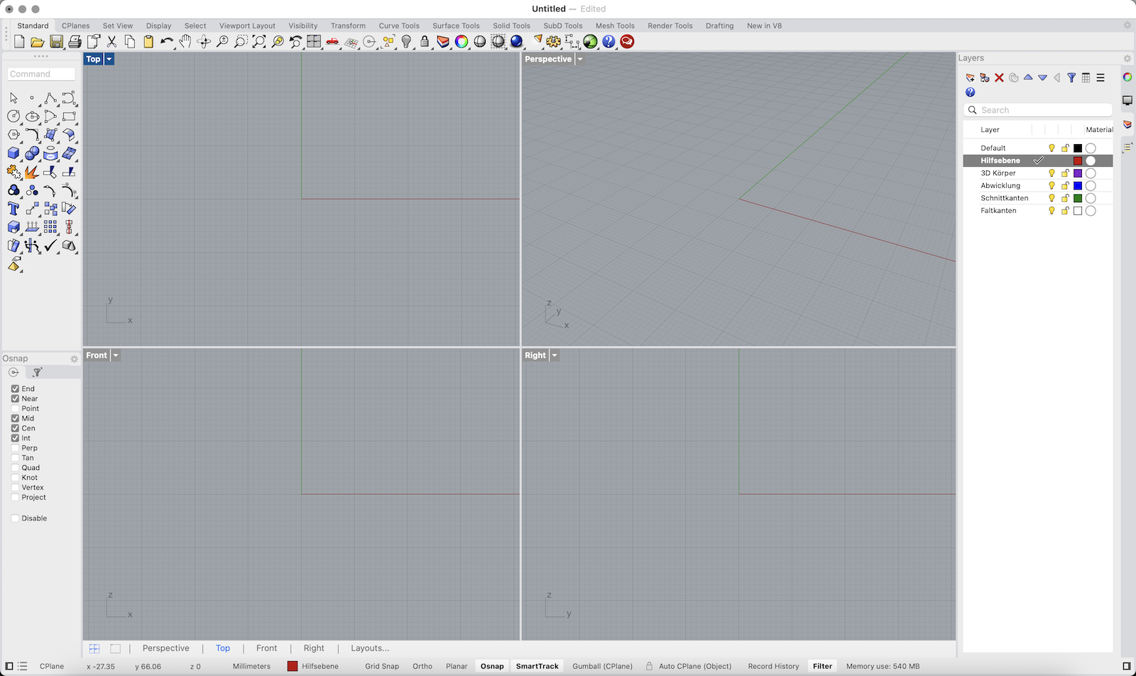
3. Add and rename more layers:
• 3D Körper (3D Body)
• Abwicklung (Unfolded)
• Schnittkanten (Cut Edges)
• Faltkanten (Fold Edges)
Use the colored squares next to each layer name to assign different colors and keep things visually organized.
Continue here for Dodecahedron
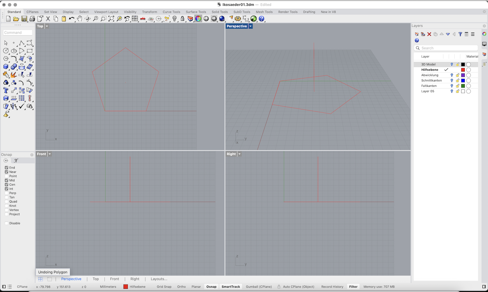
Draw a Reference Circle and Polygon
1. Make sure Hilfsebene is the active layer (click its checkmark).
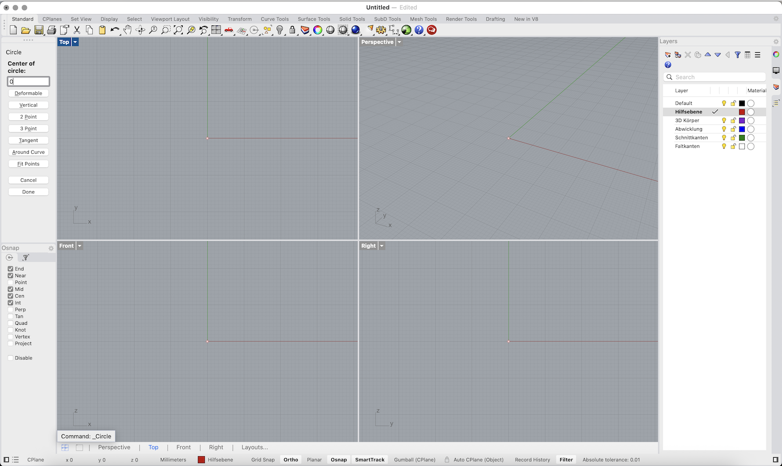
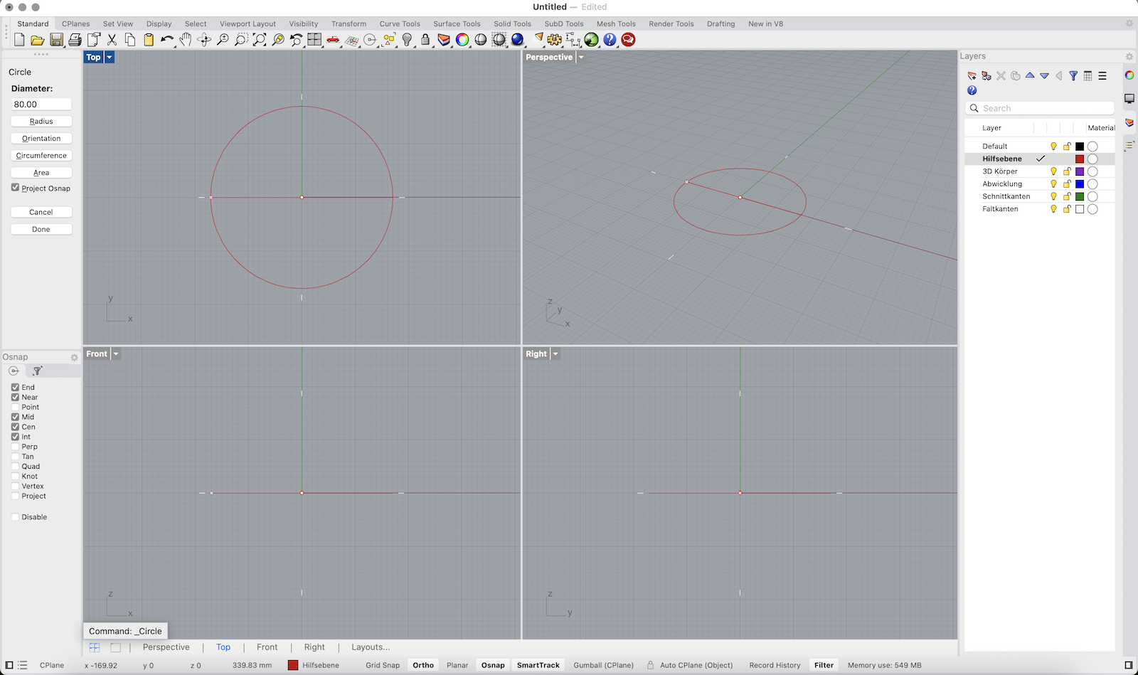
2. In the Top view, type Circle or click the Circle tool in the left toolbar.
3. Click the origin or type 0 as the center point. Then enter a diameter, e.g., 80.
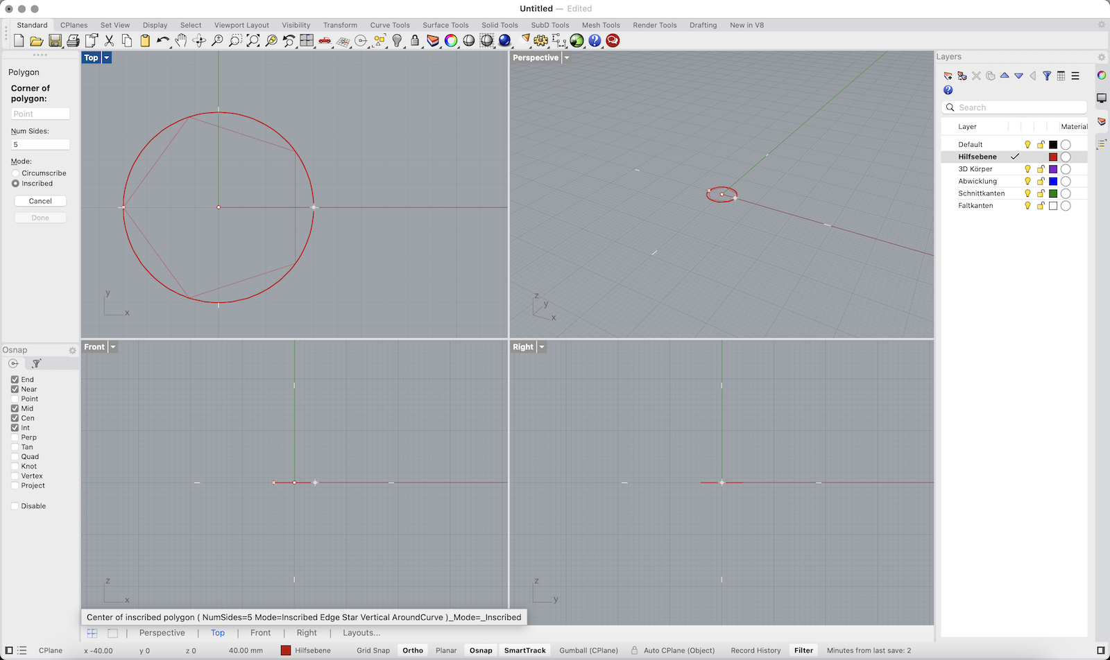
4. Next, type Polygon or select the Polygon tool. Set number of sides to 5 to create a pentagon.
5. Use Inscribed mode and snap to the center of the circle (use Center Osnap).
6. Important: Before clicking the final point, move your mouse to ensure that one side of the polygon is aligned vertically (parallel to the Y-axis).
• You can do this by snapping the final corner of the polygon directly left or right from the center using Ortho mode.
This orientation is crucial for symmetrical unfolding later! You should now have a circle with a pentagon inside.
Create a Side Face
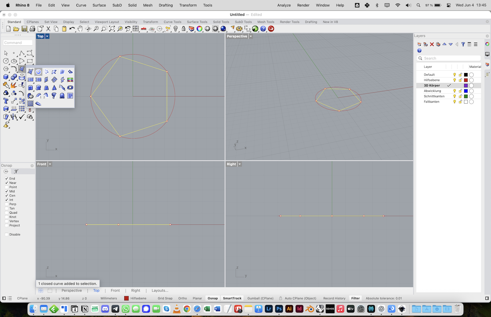
1. Switch to the 3D Körper layer and select the polygon you just drew.
2. Type PlanarSrf or go to Surface > Planar Curves to turn the polygon into a surface.
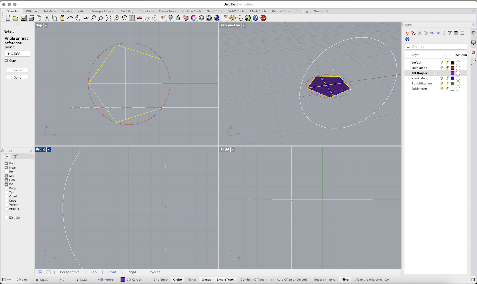
3. With the surface selected, type Rotate3D and press Enter.
4. Rhino will ask for the axis of rotation:
• In the Top view, click the lower right edge of the polygon — first at the bottom right corner, then at the top right corner of that edge. This defines a vertical axis.
5. Now set the rotation base angle:
• Move your mouse horizontally (along the X-axis) to set the base reference direction (angle = 0°).
6. Type 116.565 and press Enter.
• This rotates the face upward by the correct angle for a dodecahedron (based on its internal dihedral angle).
• Make sure Copy = Yes is selected so that the original face stays in place and a rotated copy is created.
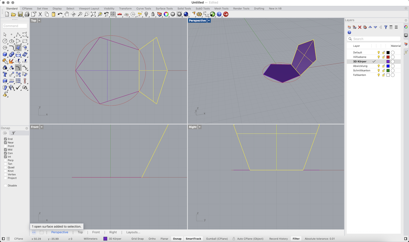
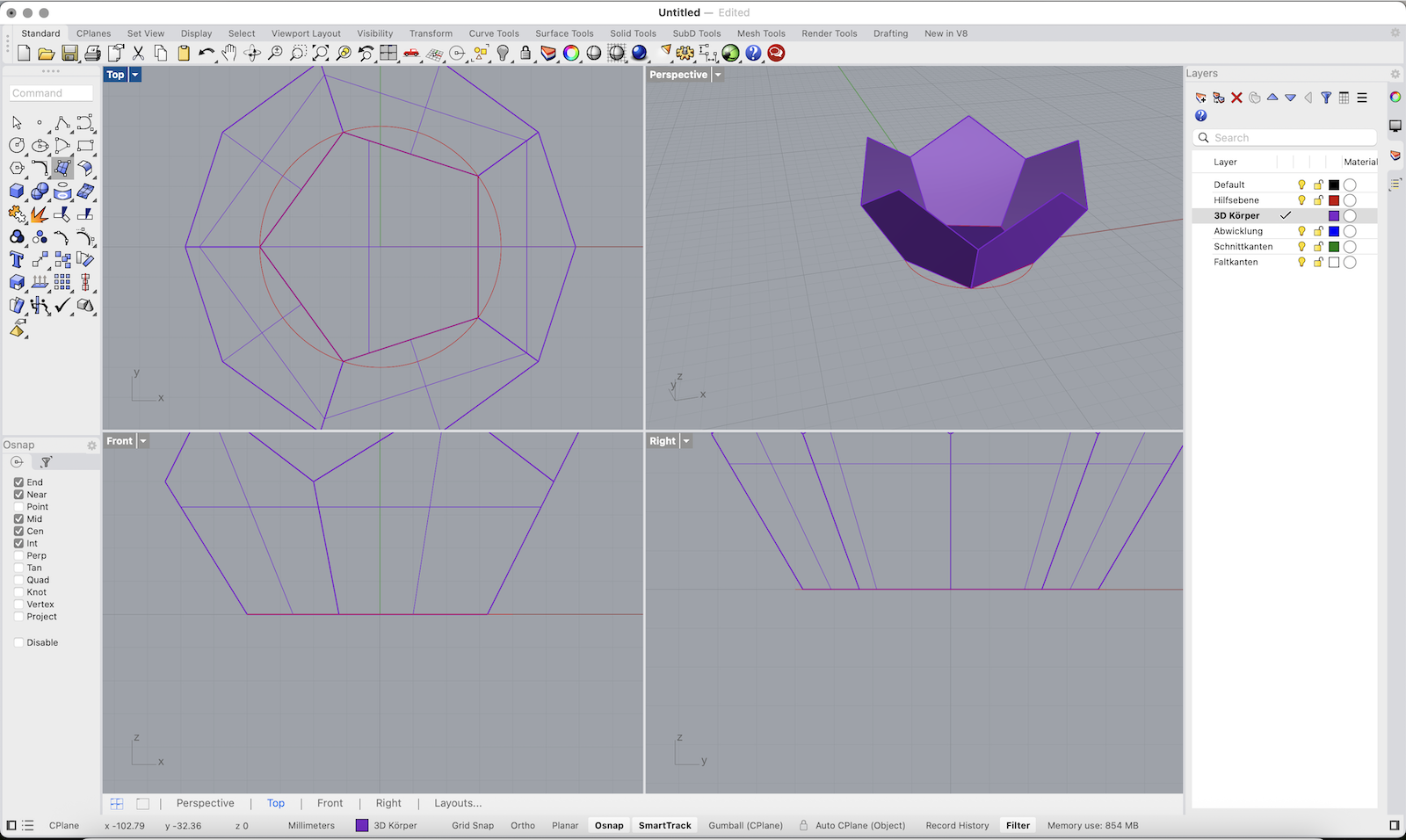
Rotate the Surface Around the Polygon
1. Select the upright polygon surface (the rotated side face).
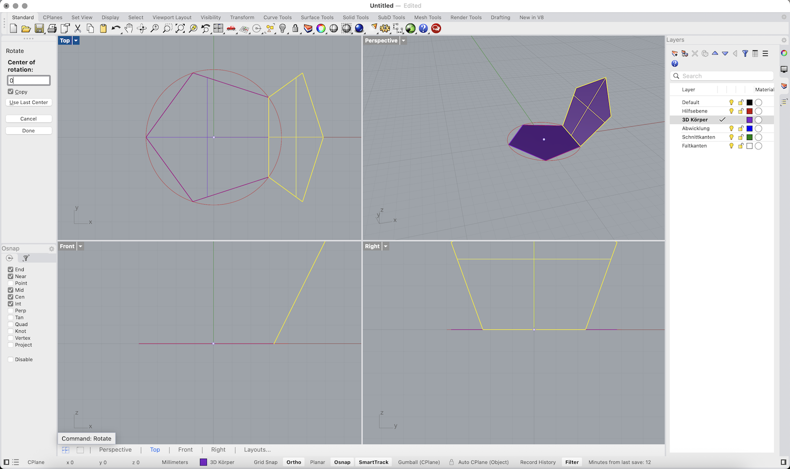
2. Type Rotate and press Enter.
3. When asked for the center of rotation, type 0 and press Enter to use the center of the circle.
4. Rhino will ask for a reference point to define the rotation angle:
• Click one corner of the base polygon (e.g. the bottom right vertex of the base).
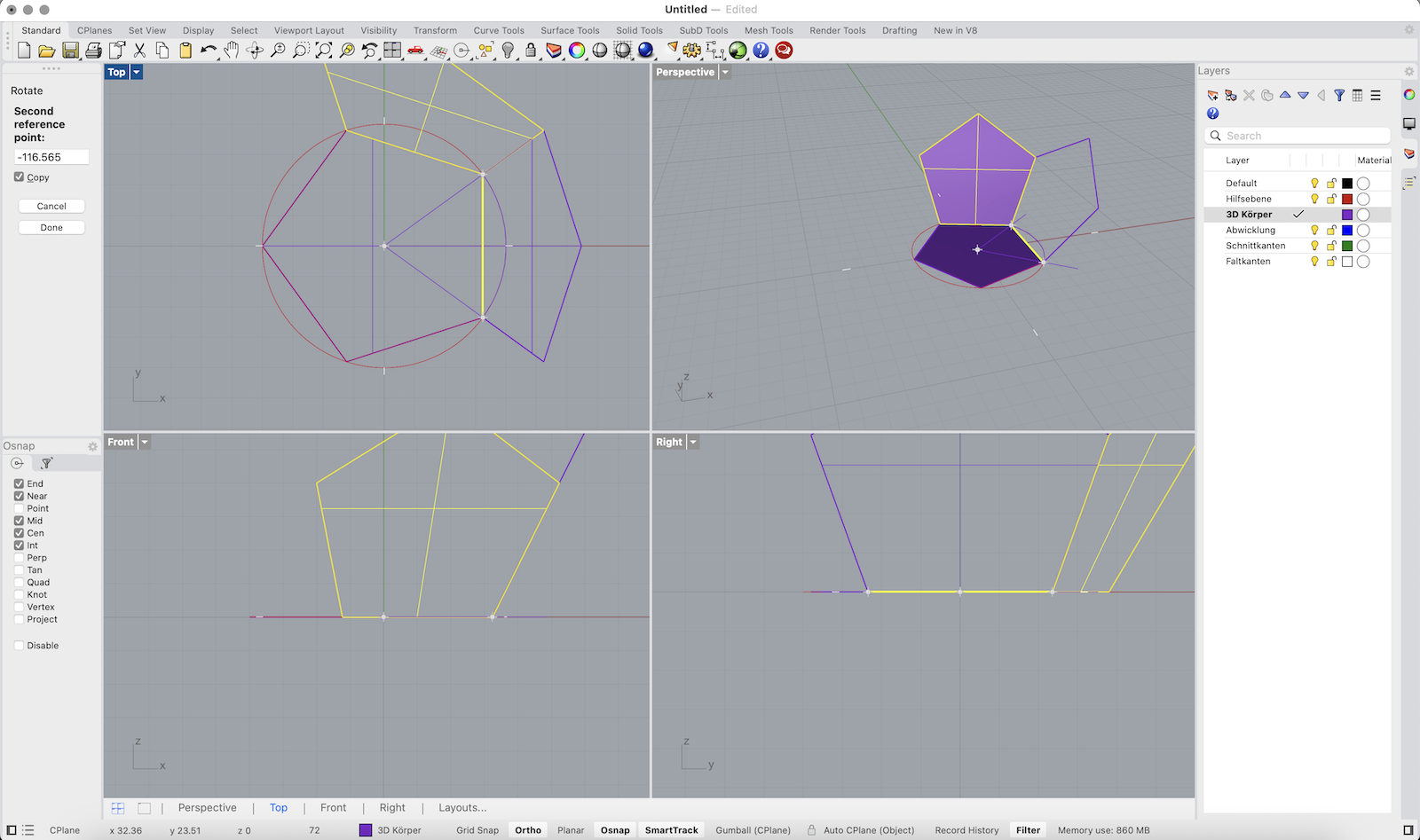
• Then click the next corner in clockwise direction — this defines the 72° step (for a pentagon).
5. In the command line, make sure Copy = Yes so each rotation adds a new face.
6. Press Enter to complete the command.
Repeat this process 4 more times to duplicate the face around all sides of the polygon.
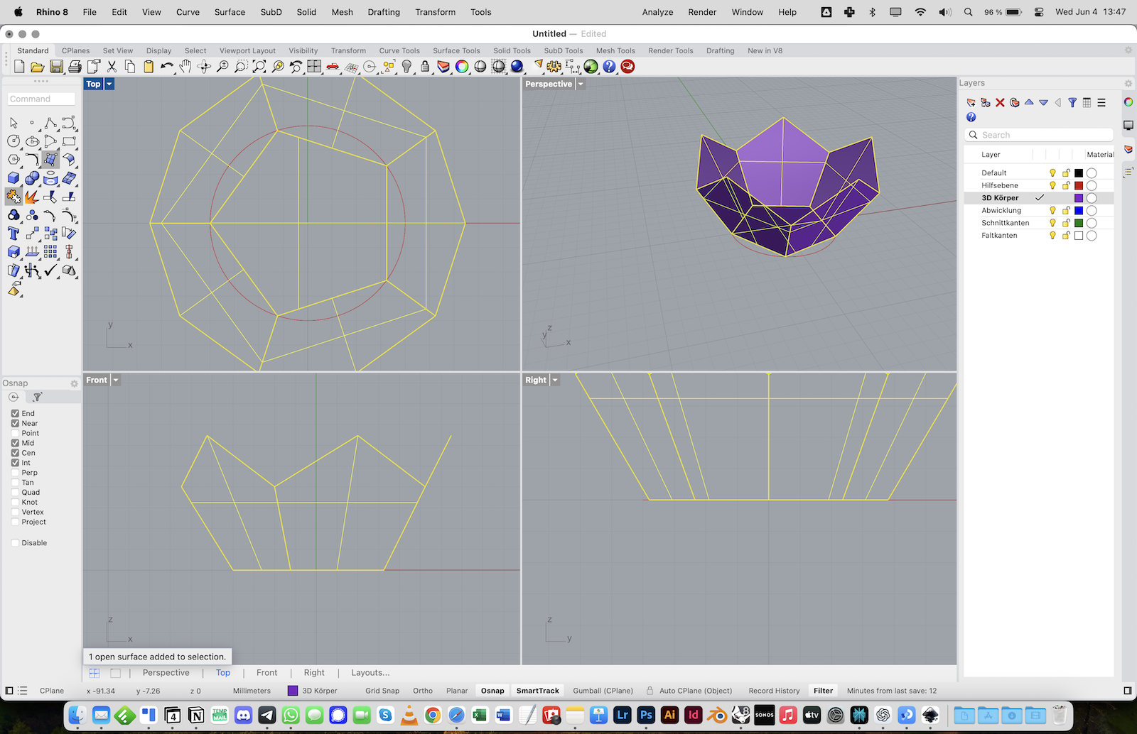
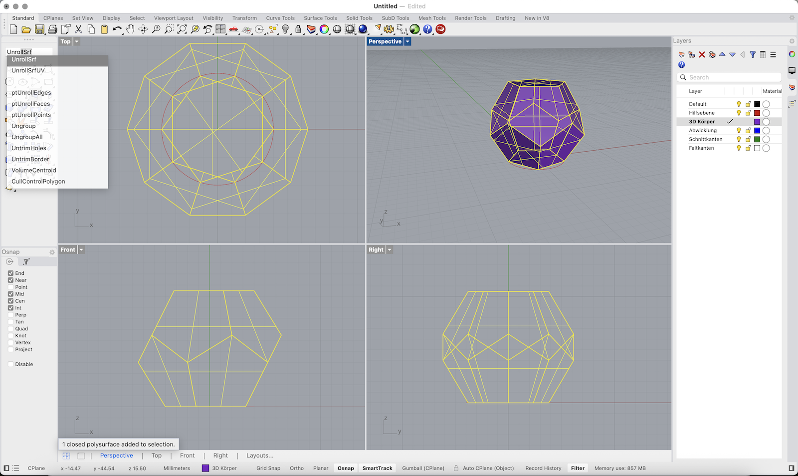
Complete the 3D Dodecahedron
1. Select all the polygon surfaces you created so far.
2. Type Join and press Enter to combine them into a single polysurface.
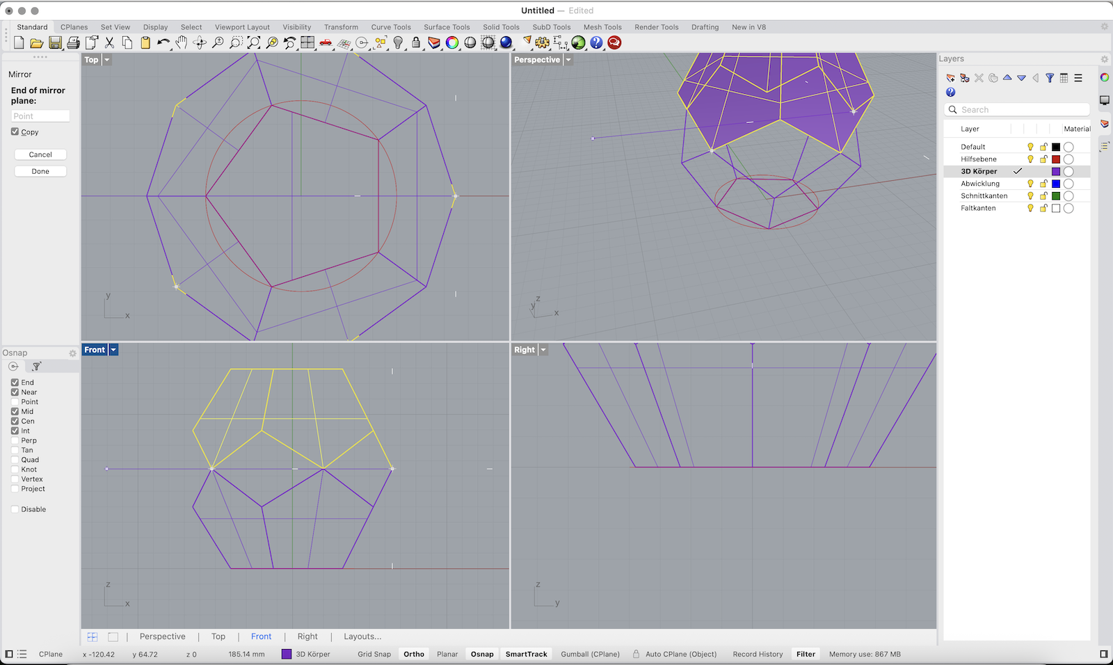
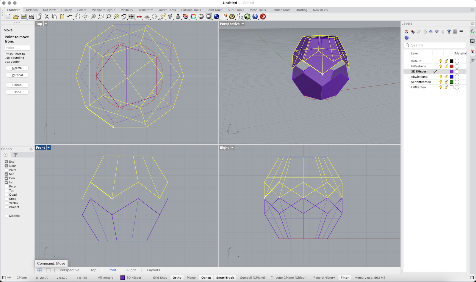
3. Type Mirror and press Enter.
• In the Front view, click two points along the horizontal (X) axis to mirror the joined surface upward.
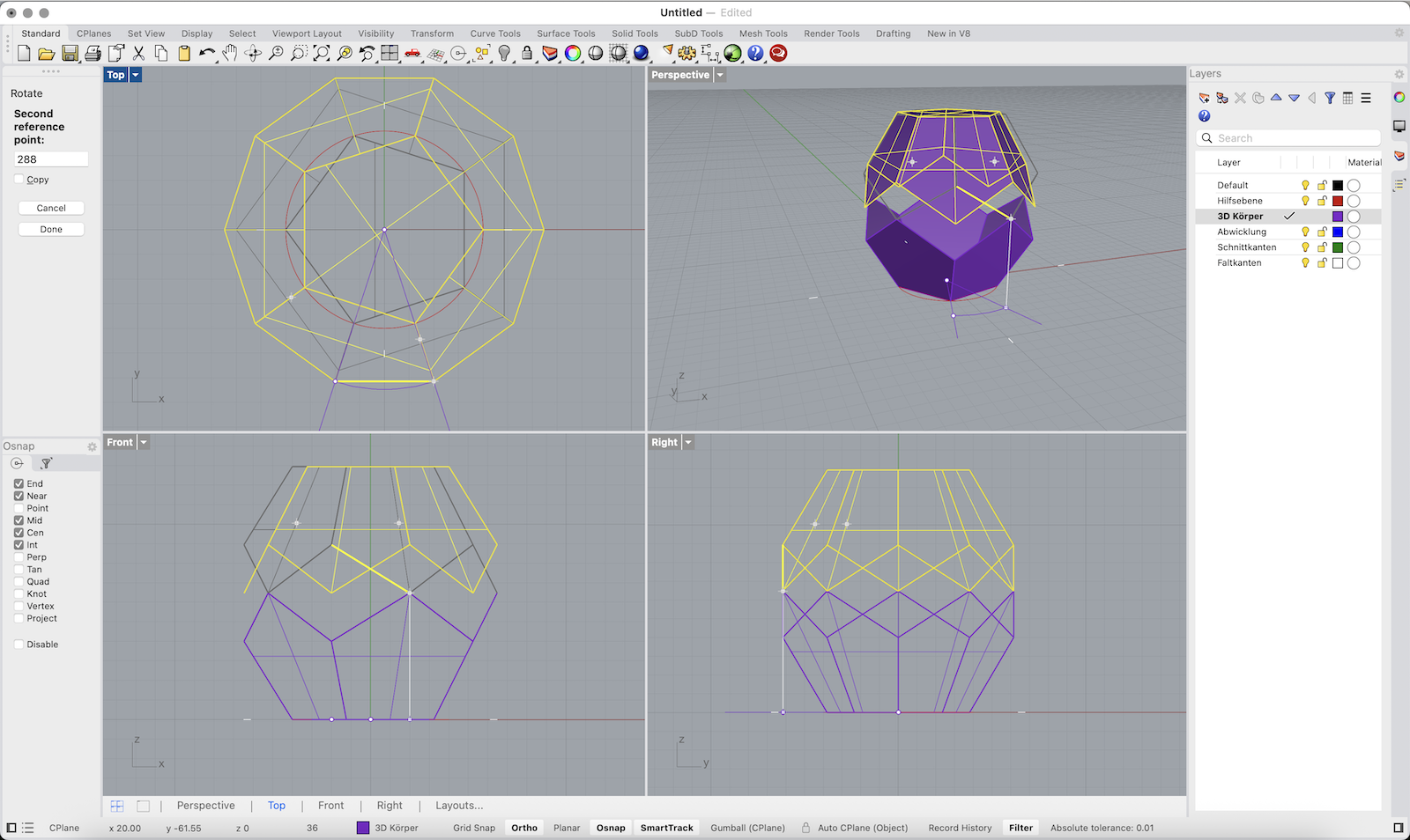
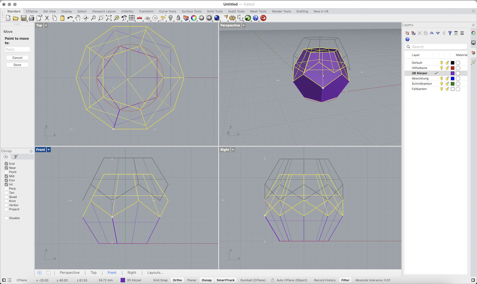
4. With the mirrored copy still selected, type Rotate.
• In the Top view, select the center of the base as the rotation center.
• Then click on one corner of the base polygon, and rotate the mirrored top until it aligns with the next half-corner.
5. Use Move to bring the rotated top half downward into position so it connects perfectly with the lower half.
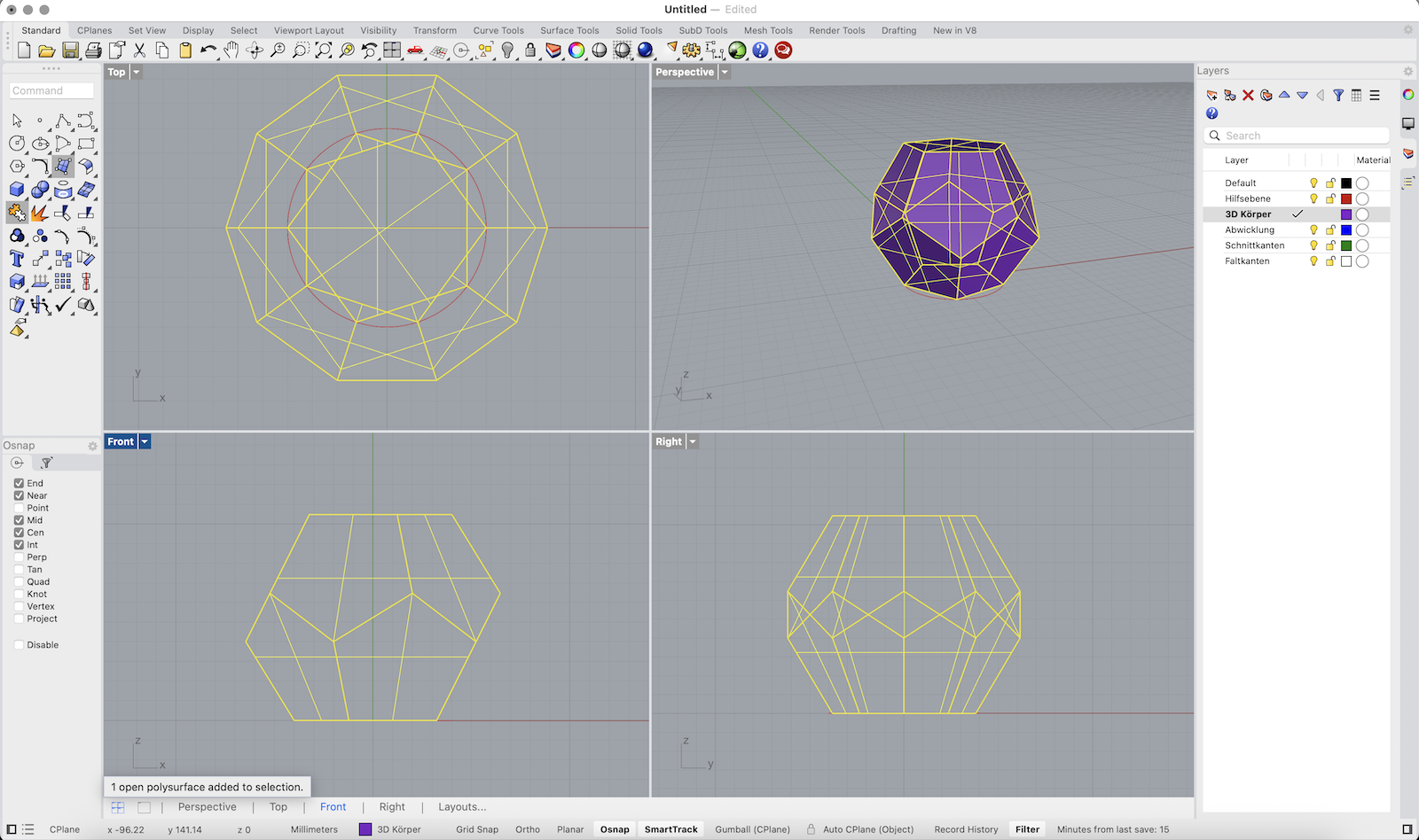
6. Finally, select all parts and type Join to create one closed 3D solid.
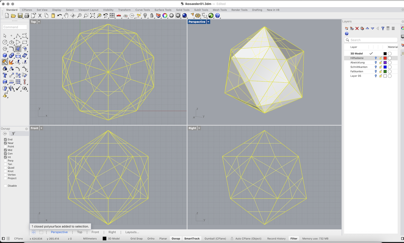
Continue here for Icosahedron
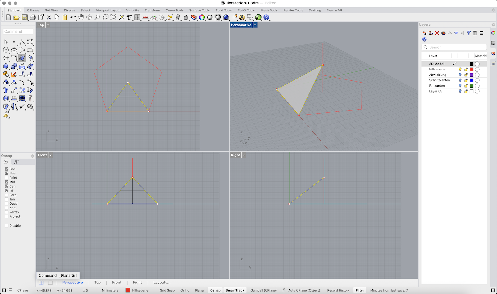
Construct the Base Triangle
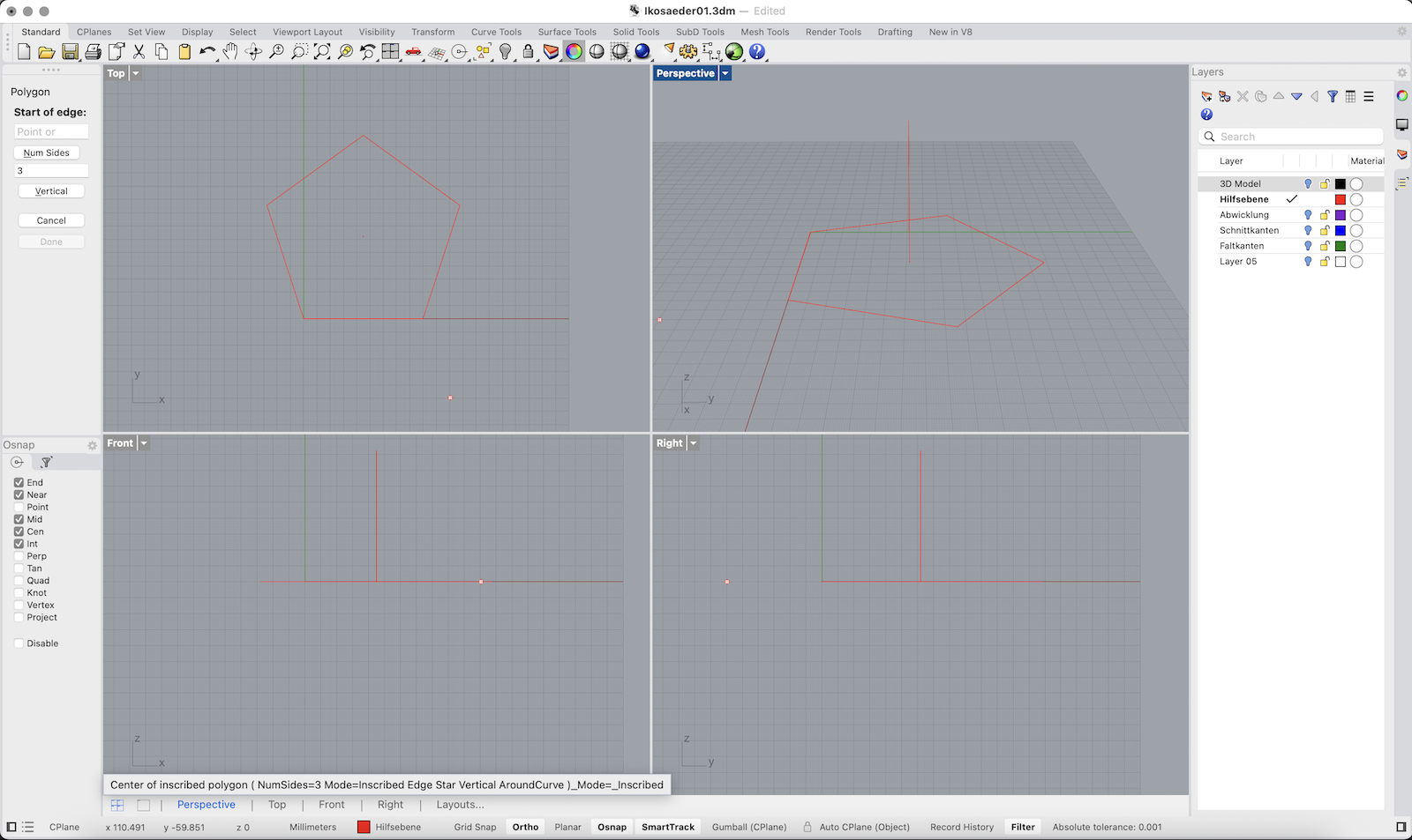
1. In the Top viewport, type Polygon and press Enter.
2. Set the number of sides to 5, and draw a horizontal pentagon using the Edge option with a side length of 80 mm.
3. Type Line and draw a vertical line from the center of the pentagon with a length of 80mm
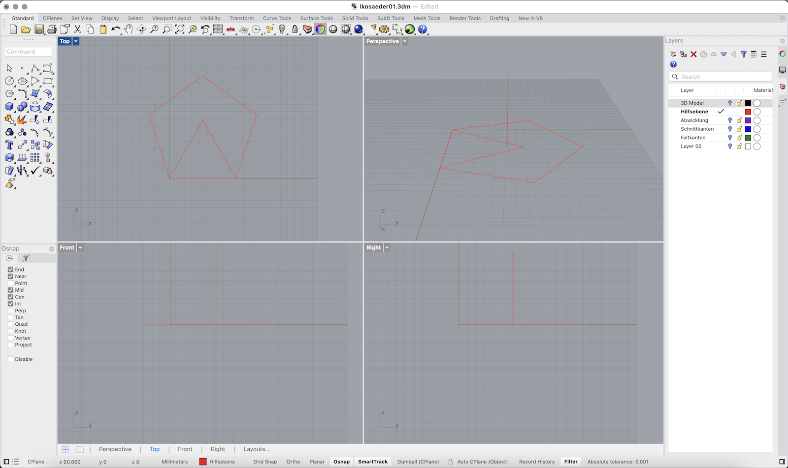
4. Type Polygon again and set it to 3 sides.
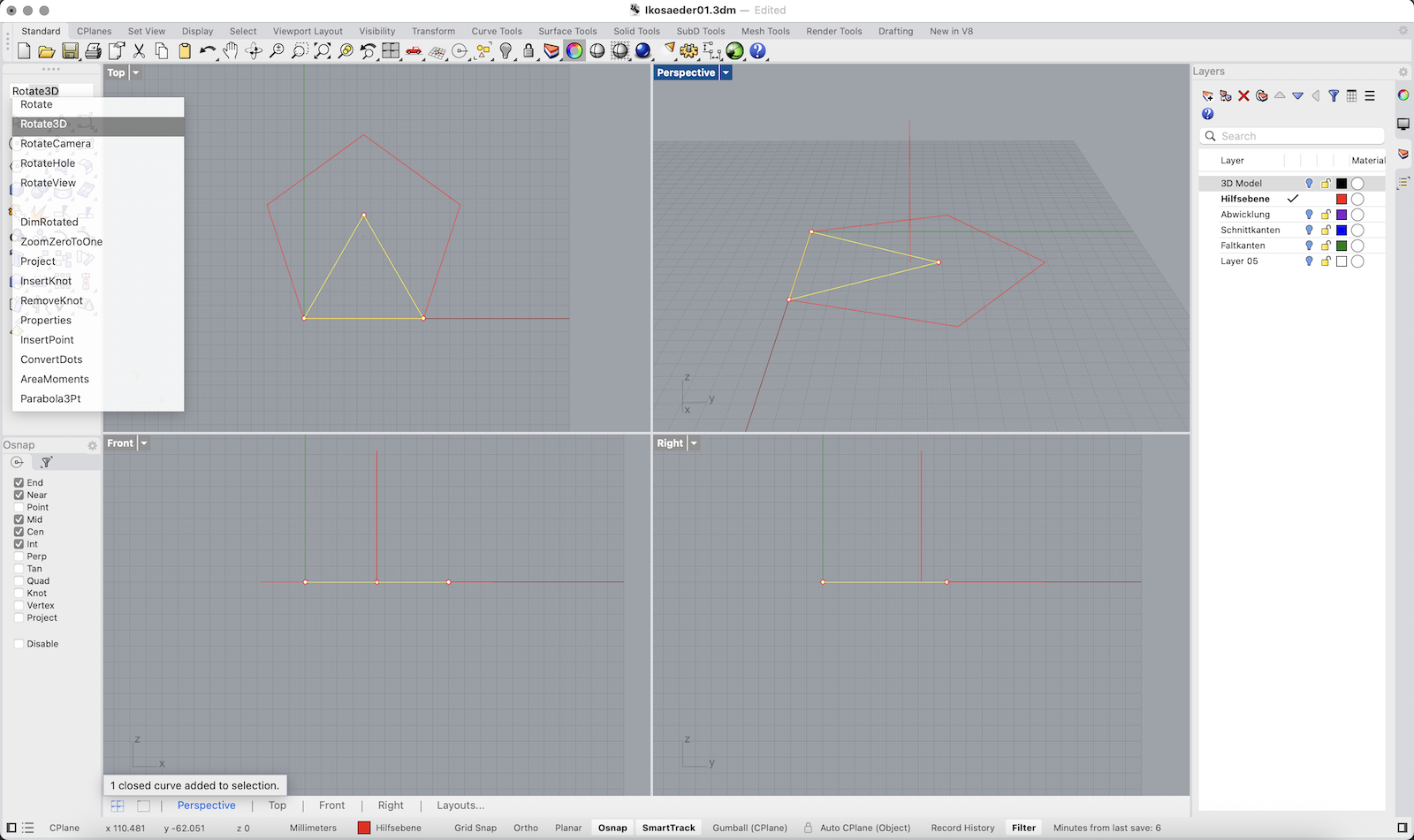
5. Activate the Edge option and draw an equilateral triangle with one side also measuring 80 mm aligning exactly with one side of the pentagon.
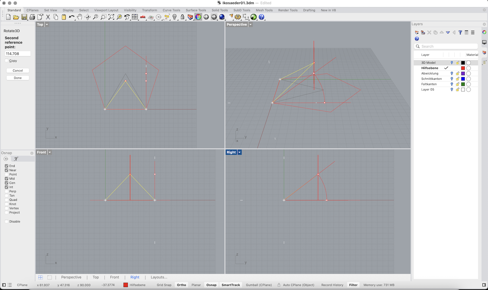
8. Use Rotate3D and rotate the triangle upward using the shared edge as the rotation axis and the centerline as reference until the top of the triangle and the centerline intersect (Intersect Osnap).
Convert Triangle to 3D Surface and Rotate Around Centerline
1. Switch to the 3D Model layer.
2. Select the triangular curve you just drew (the planar triangle).
3. Type PlanarSrf and press Enter to create a surface from the triangle’s boundary.
4. With the surface still selected, type Rotate and hit Enter. Make sure Copy=Yes is enabled.
5. Rotate the surface around the center line. Use the corners of the pentagon as reference.
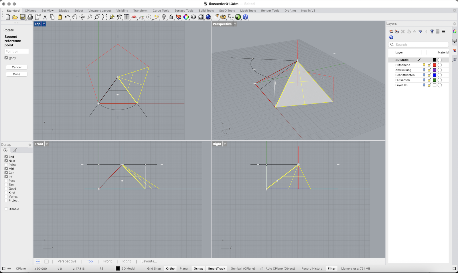
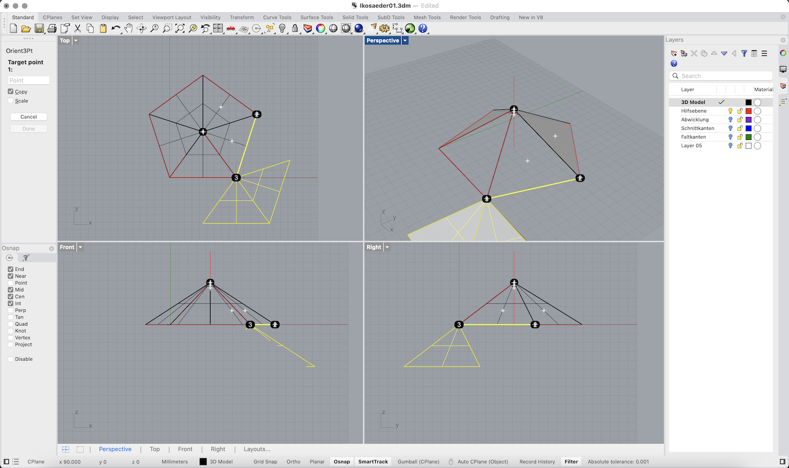
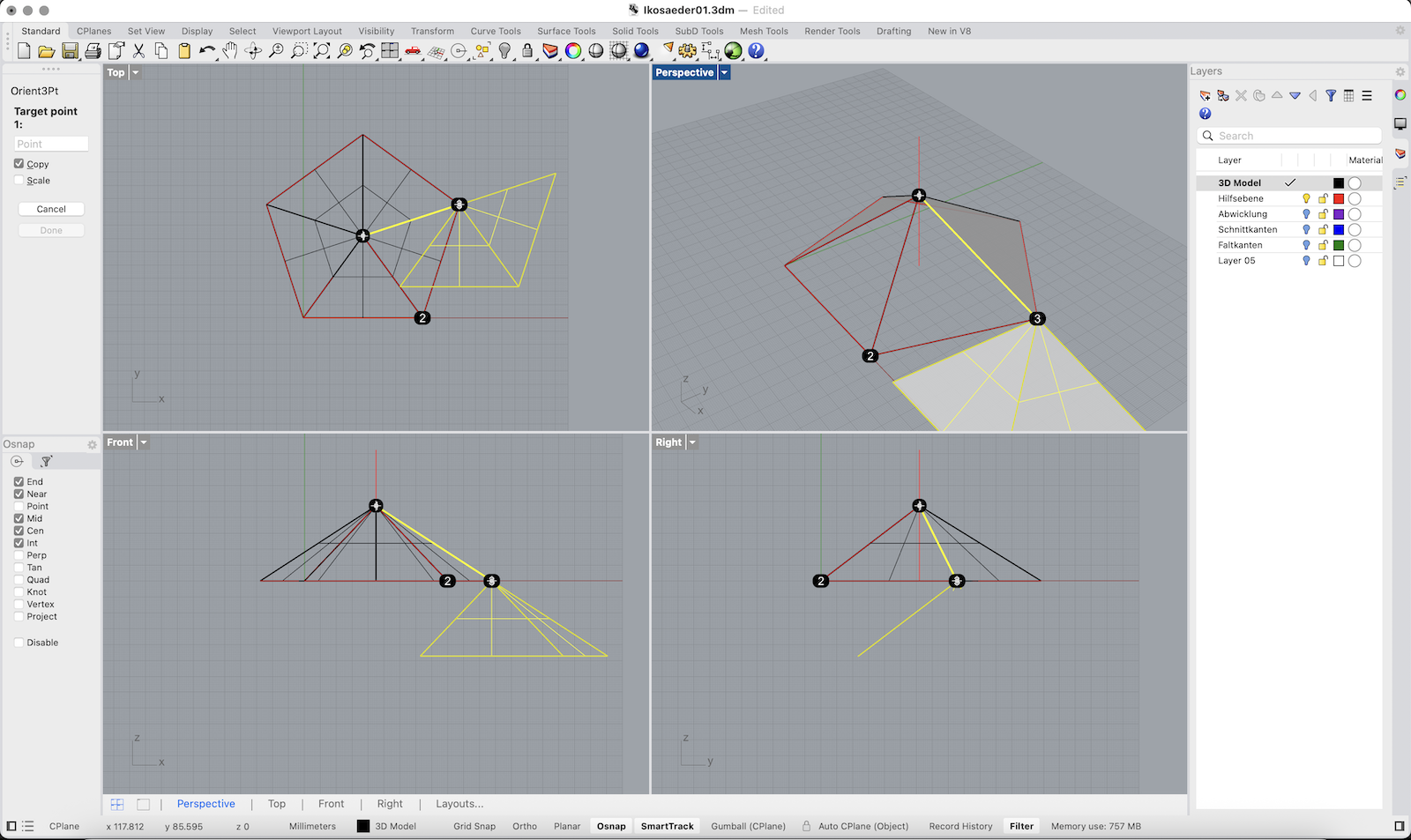
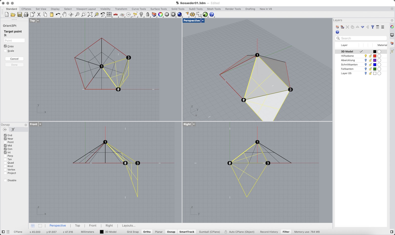
Orient Two Adjacent Triangles
1. Select the two triangular surfaces.
2. Type Orient3Pt and press Enter.
3. For the source points (Top view): First click the triangle’s top vertex, then click the triangle’s right corner and finally the triangle’s left corner.
4. For the destination points (Top view): First click the triangle’s top vertex, then click the triangle’s left corner and finally the triangle’s right corner.
5. Make sure Copy=Yes so the originals remain.
6. After the triangles are placed, delete any duplicate surfaces left behind.
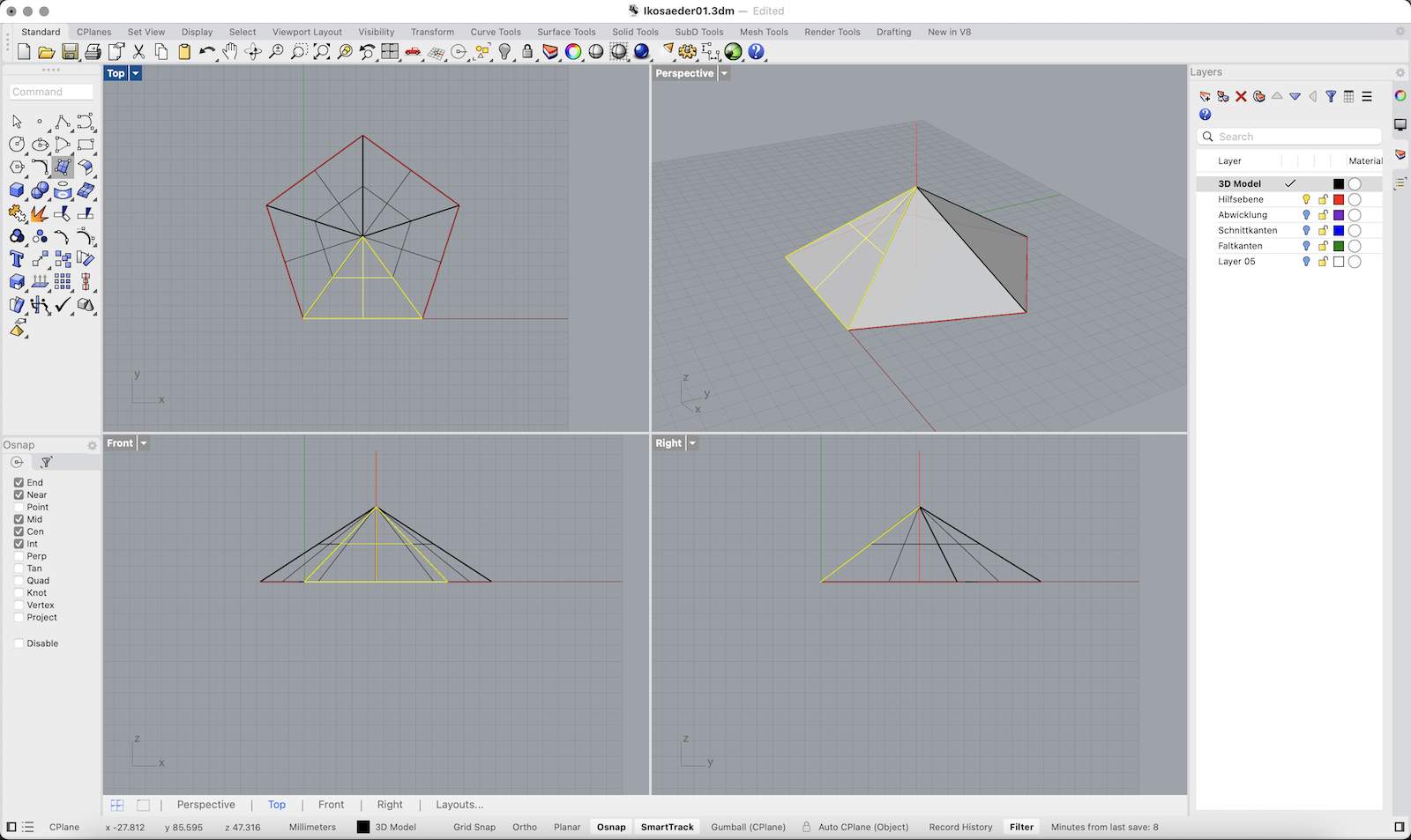
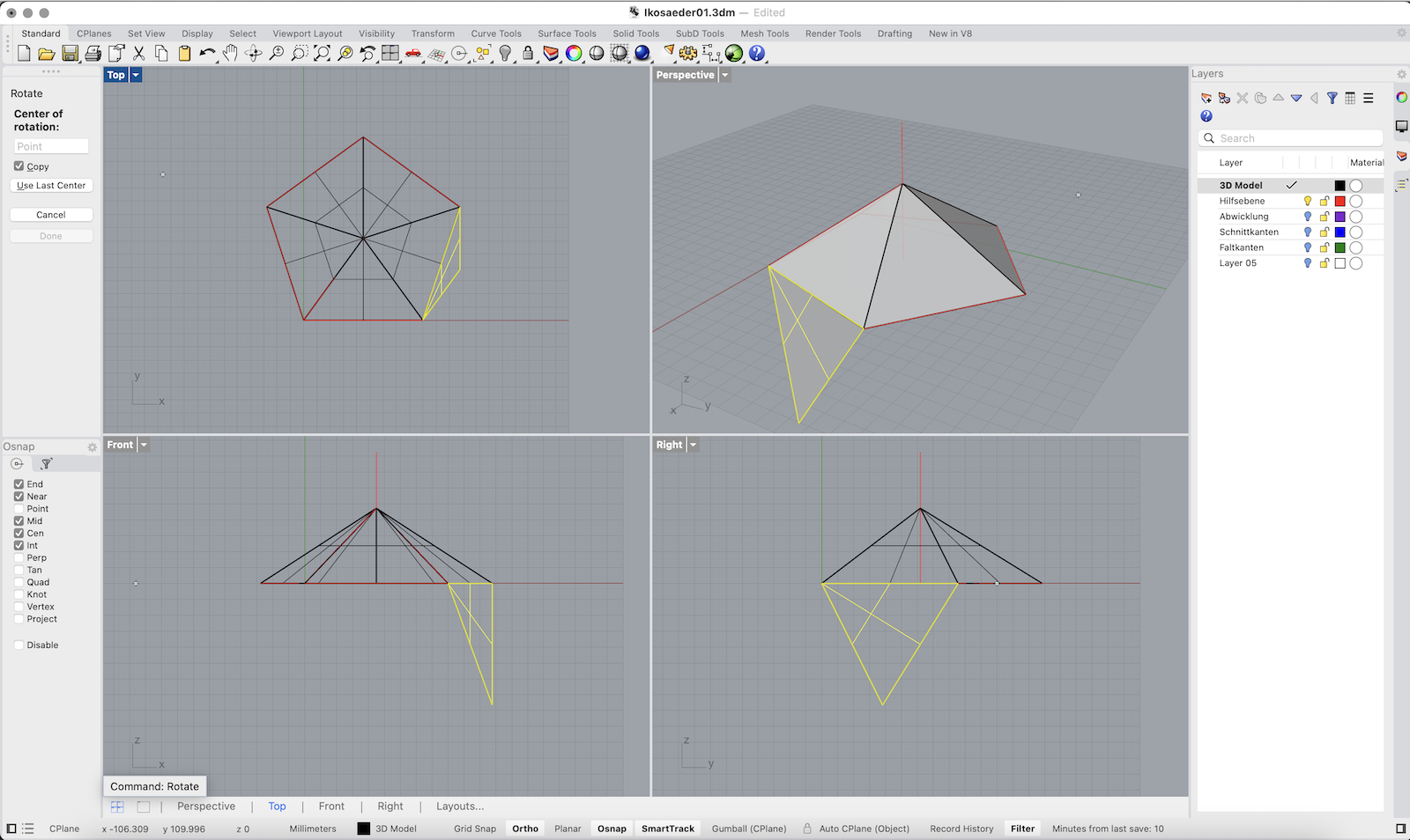
Duplicate and Rotate Triangles Around the Pentagon
1. Select the bottom triangle that’s already oriented on the pentagon.
2. Type Rotate and press Enter. Make sure Copy=Yes.
3. Click the pentagon’s center point as the rotation axis point.
4. For the reference direction, click the triangle’s base edge (so 0° is aligned).
5. Repeat the Rotate command on each newly placed triangle until all five triangle faces surround the pentagon.
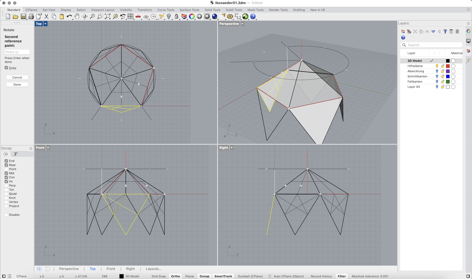
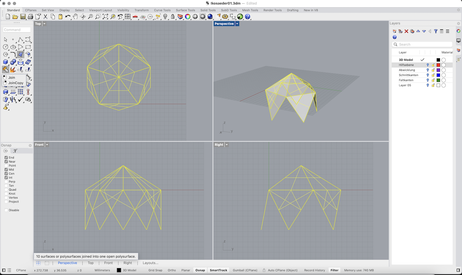
Complete the 3D Icosahedron
1. Select all the triangular surfaces and type Join to combine them into one open polysurface.
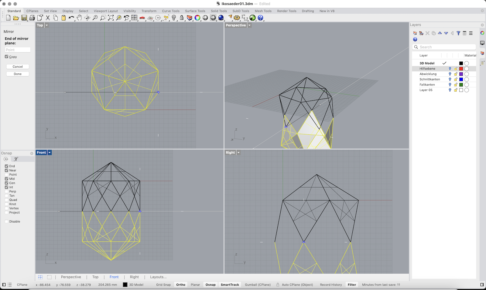
2. Type Mirror and, in the Front view, pick two points along the X-axis to mirror the joined half downward.
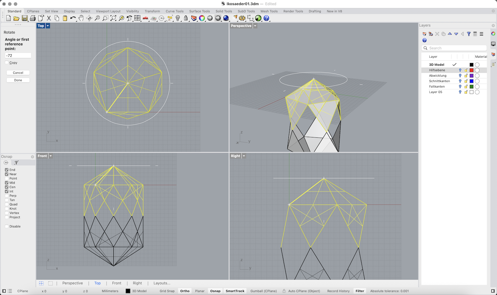
3. With the mirrored copy still selected, type Rotate and, in the Top view, pick the pentagon’s center as the rotation pivot, then click any triangle corner and rotate it into place.
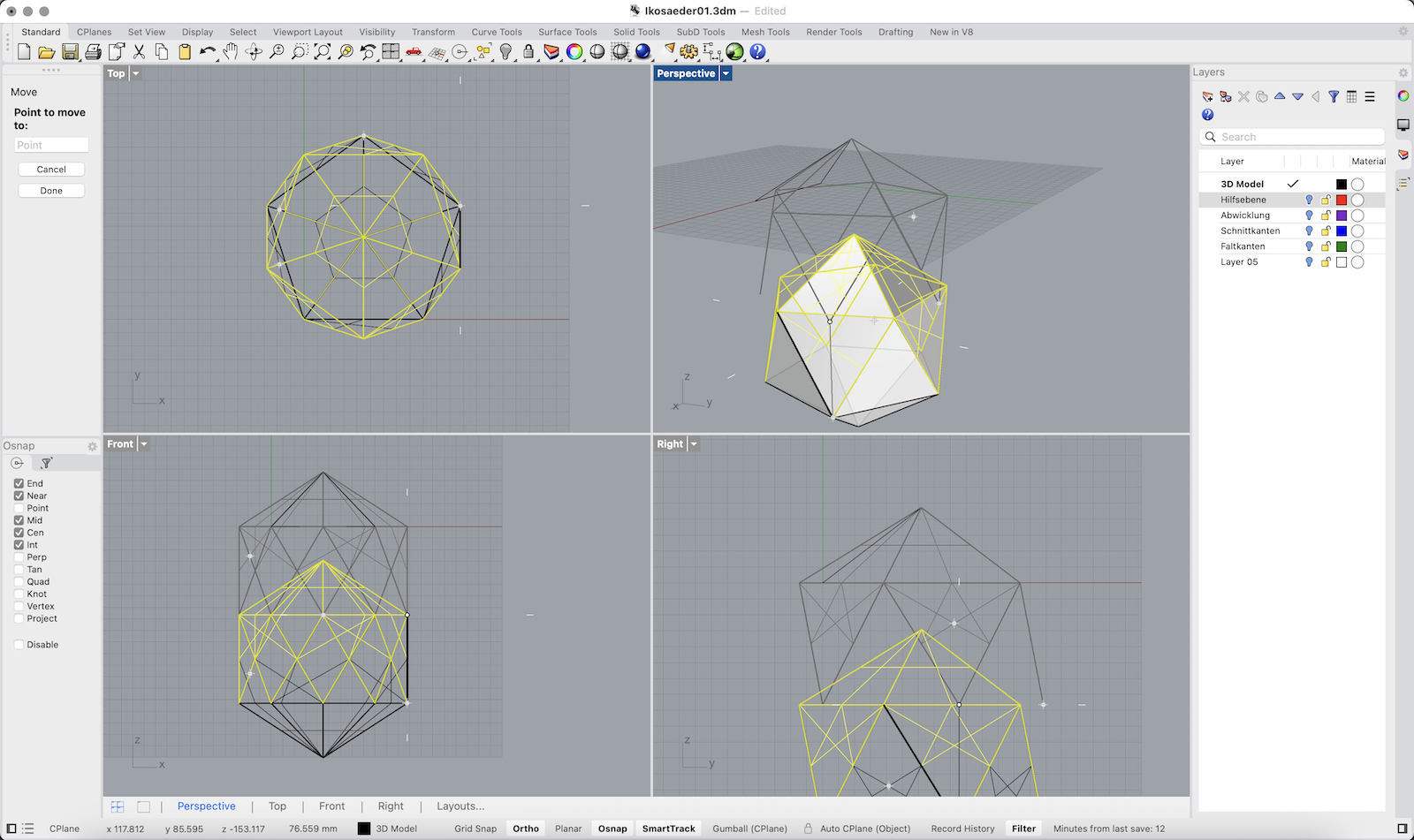
4. Use Move to lower the mirrored half so that its edges align perfectly with the original half, closing all gaps.
5. Finally, select all faces and type Join to create one closed 3D solid.
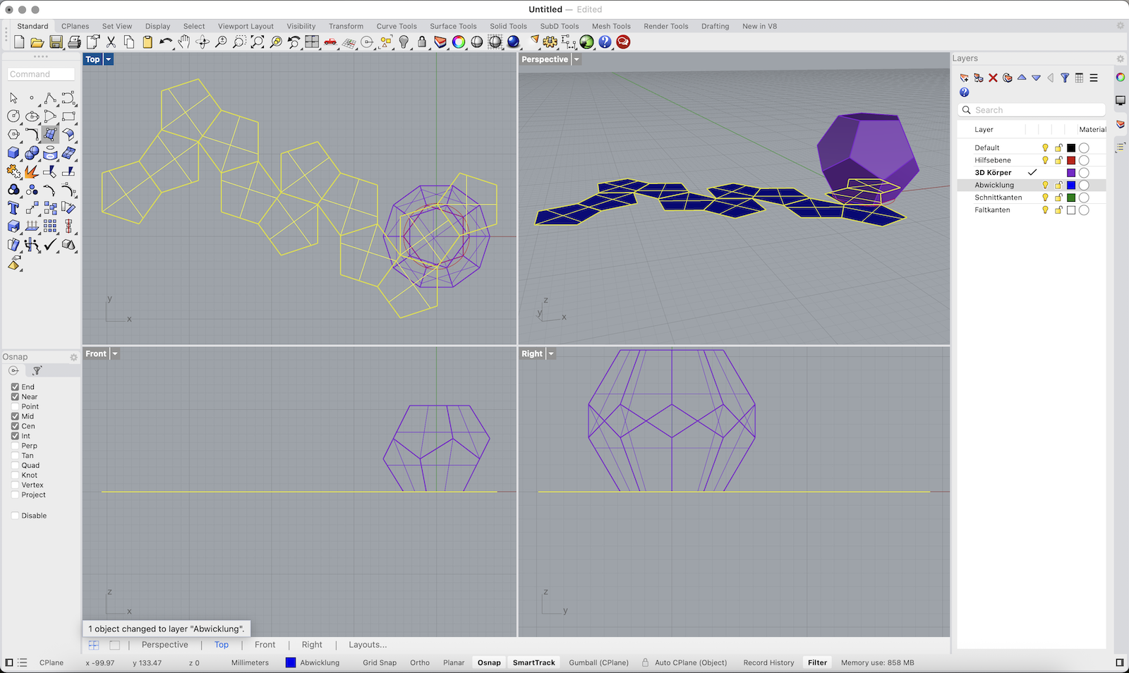
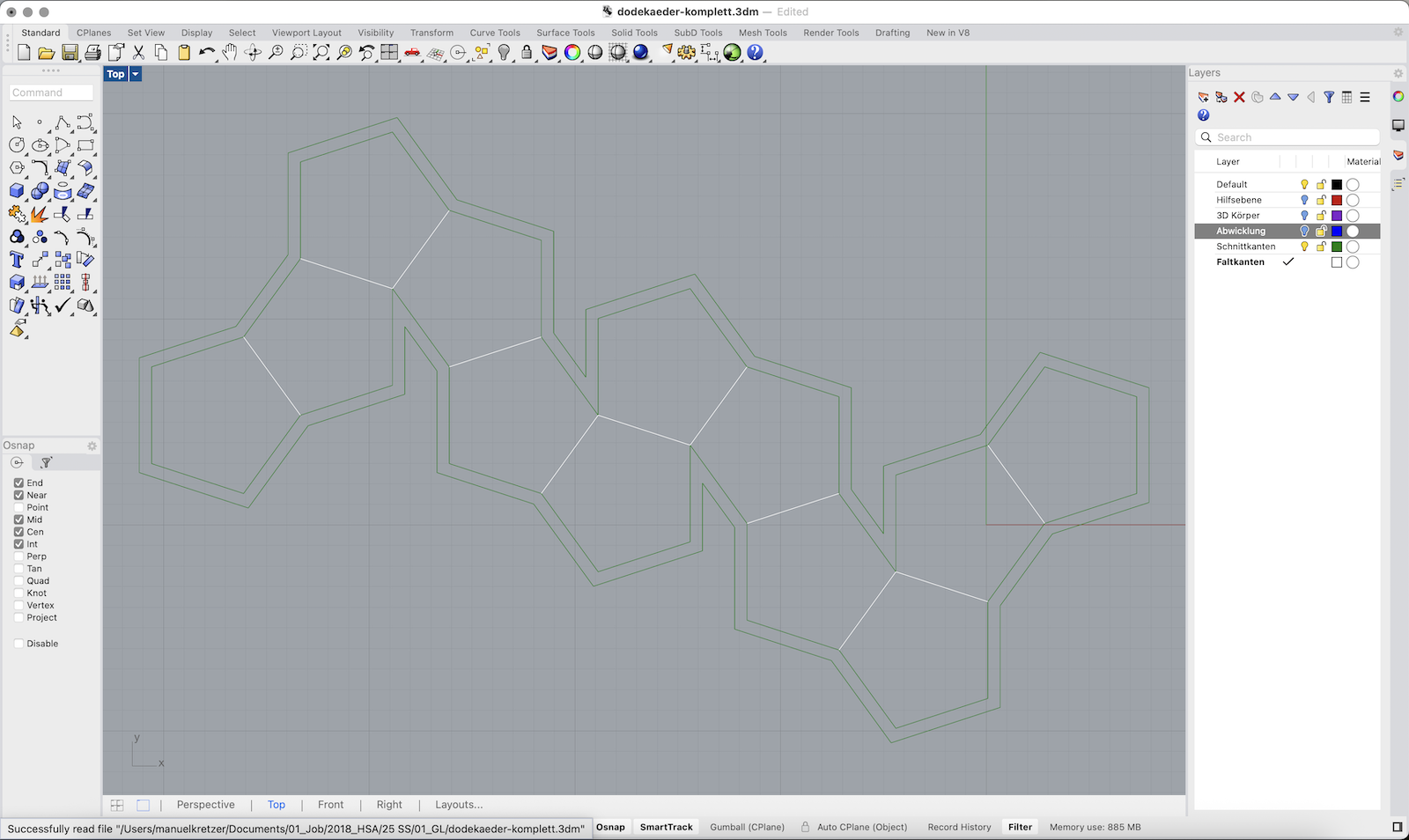
Unfold the Geometry
1. Switch to the Abwicklung (Unfolded) layer.
2. Select the entire 3D solid.
3. Type UnrollSrf and press Enter.
4. Make sure Explode = No is unchecked.
5. Press Enter to confirm and let Rhino flatten the geometry automatically.
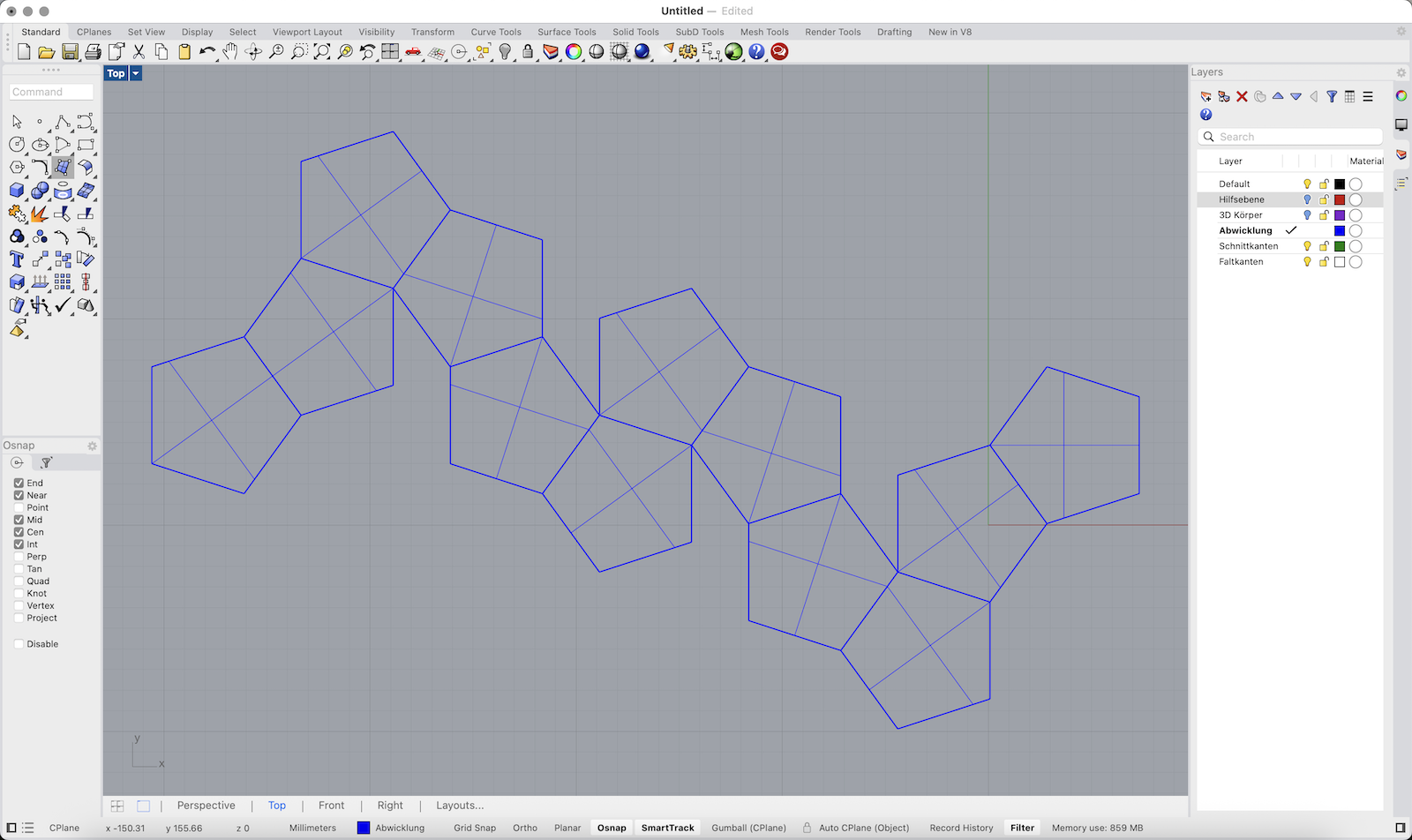
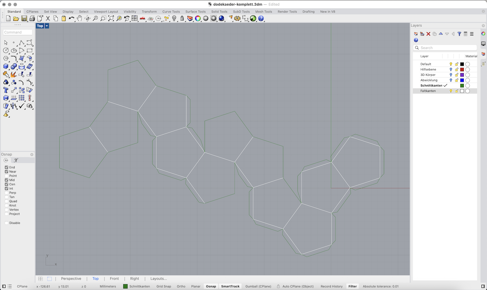
Prepare Cutting and Folding Edges
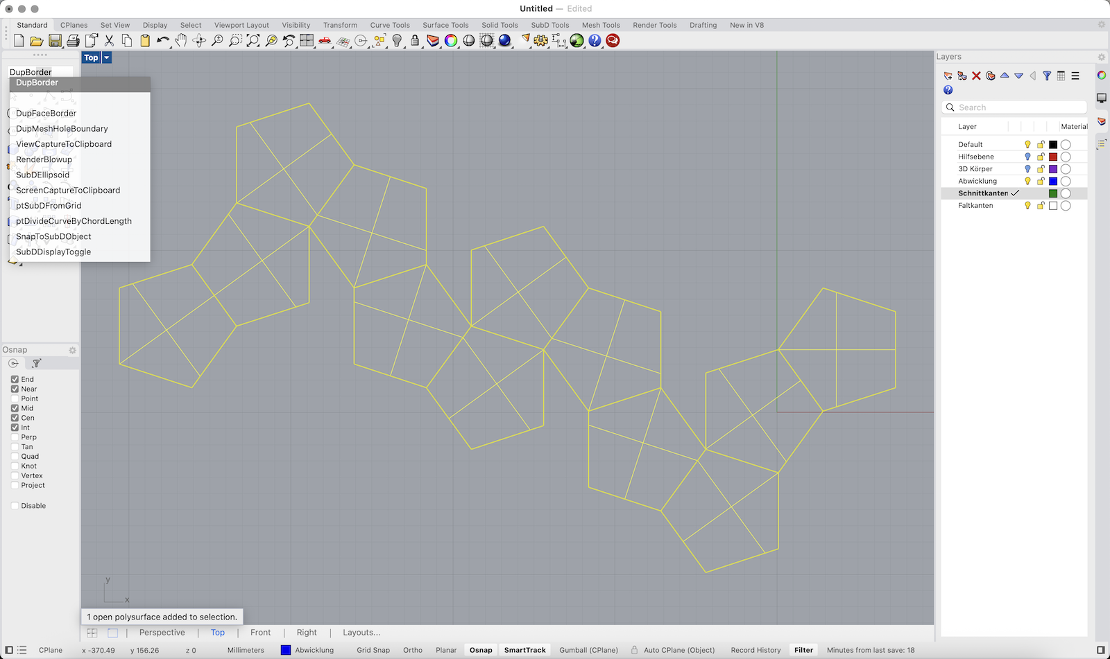
1. Switch to the Schnittkanten (Cut Edges) layer.
2. Select the unfolded surface layout.
3. Type DupBorder and press Enter to duplicate the outer boundary curves.
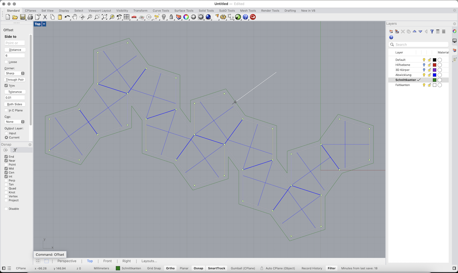
4. Type Offset and offset the border by approx. 6 mm.
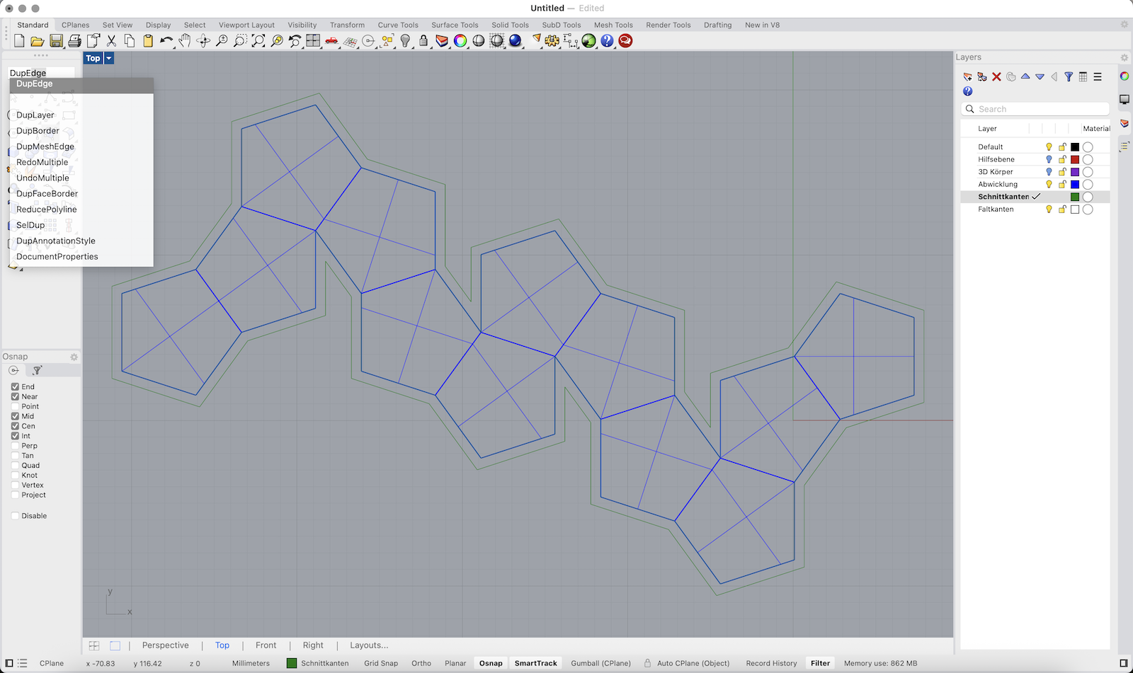
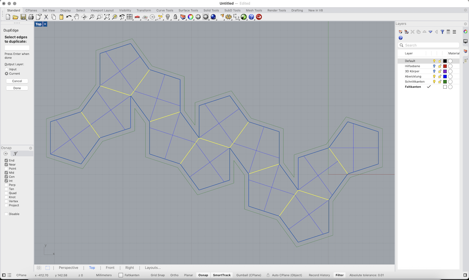
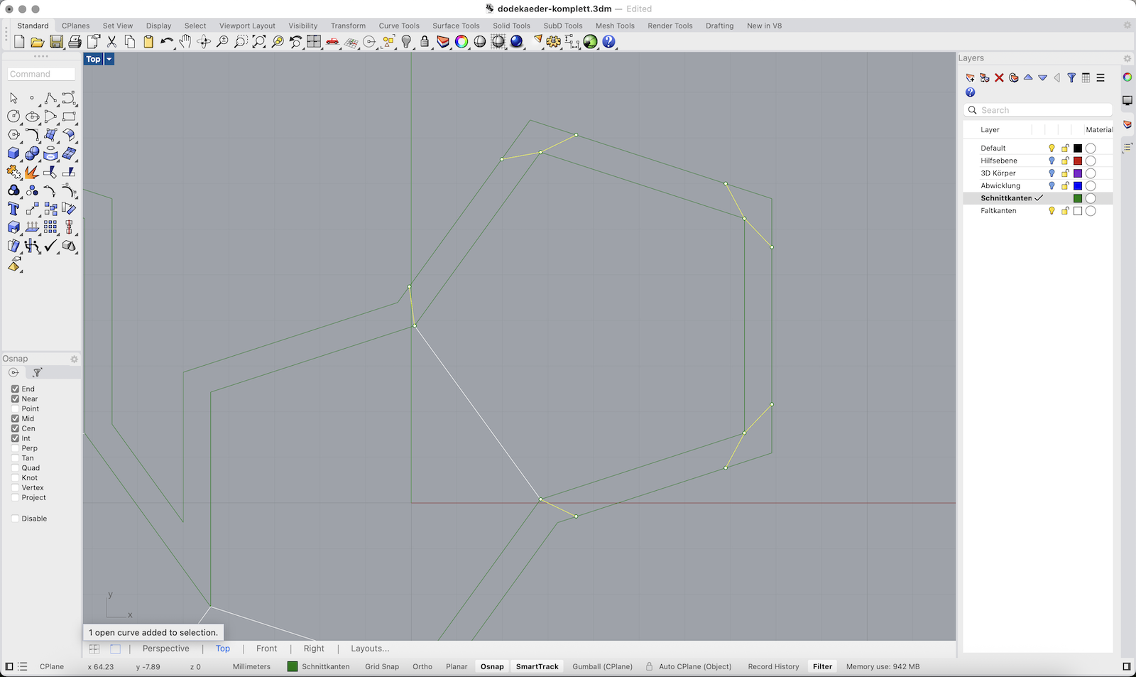
5. Type DupEdge and manually select the internal edges that represent fold lines.
6. Switch to the Faltkanten (Fold Edges) layer before duplicating these fold edges.
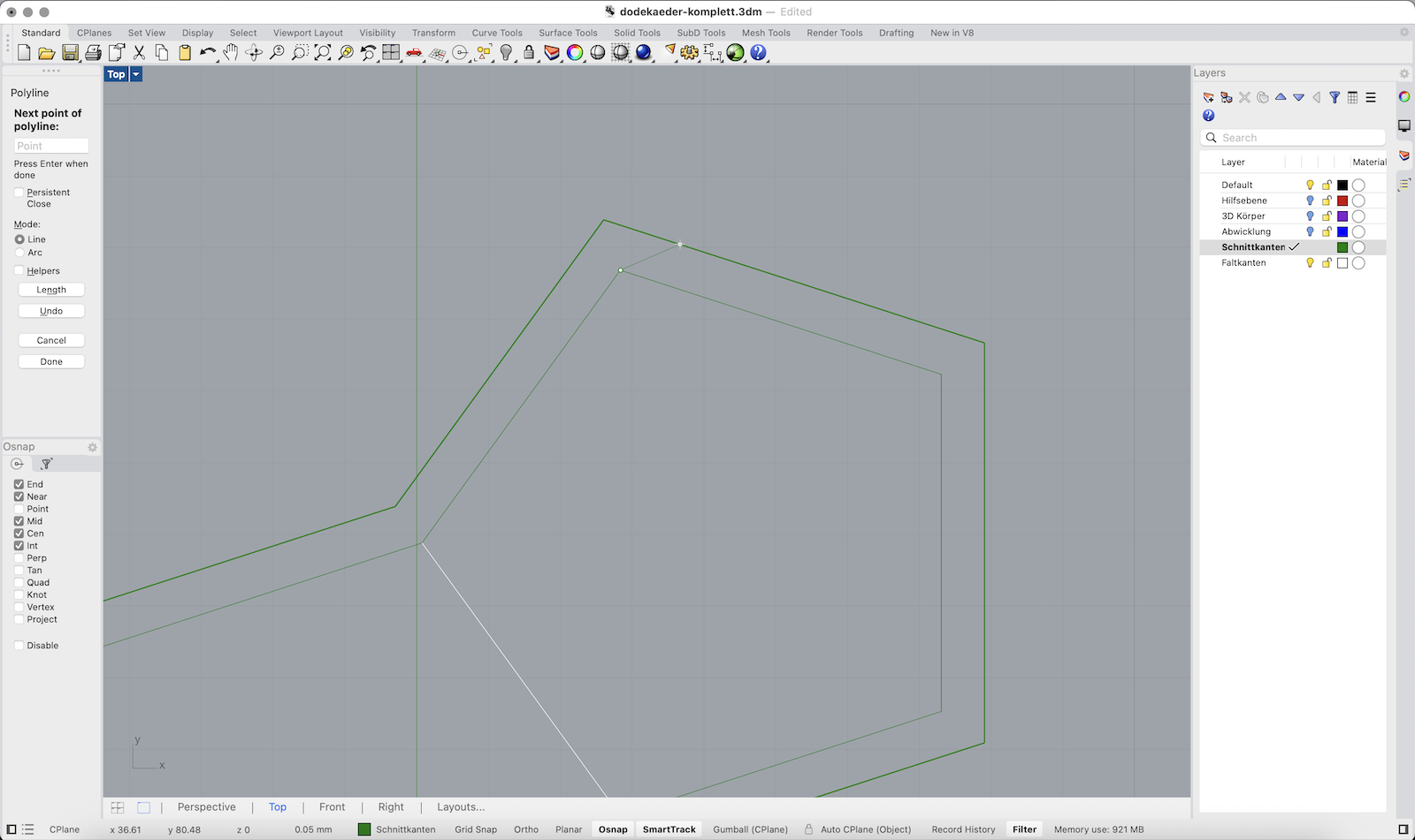
Add Glue Joints
1. Use Polyline to draw a flap extending from one edge of a polygon surface.
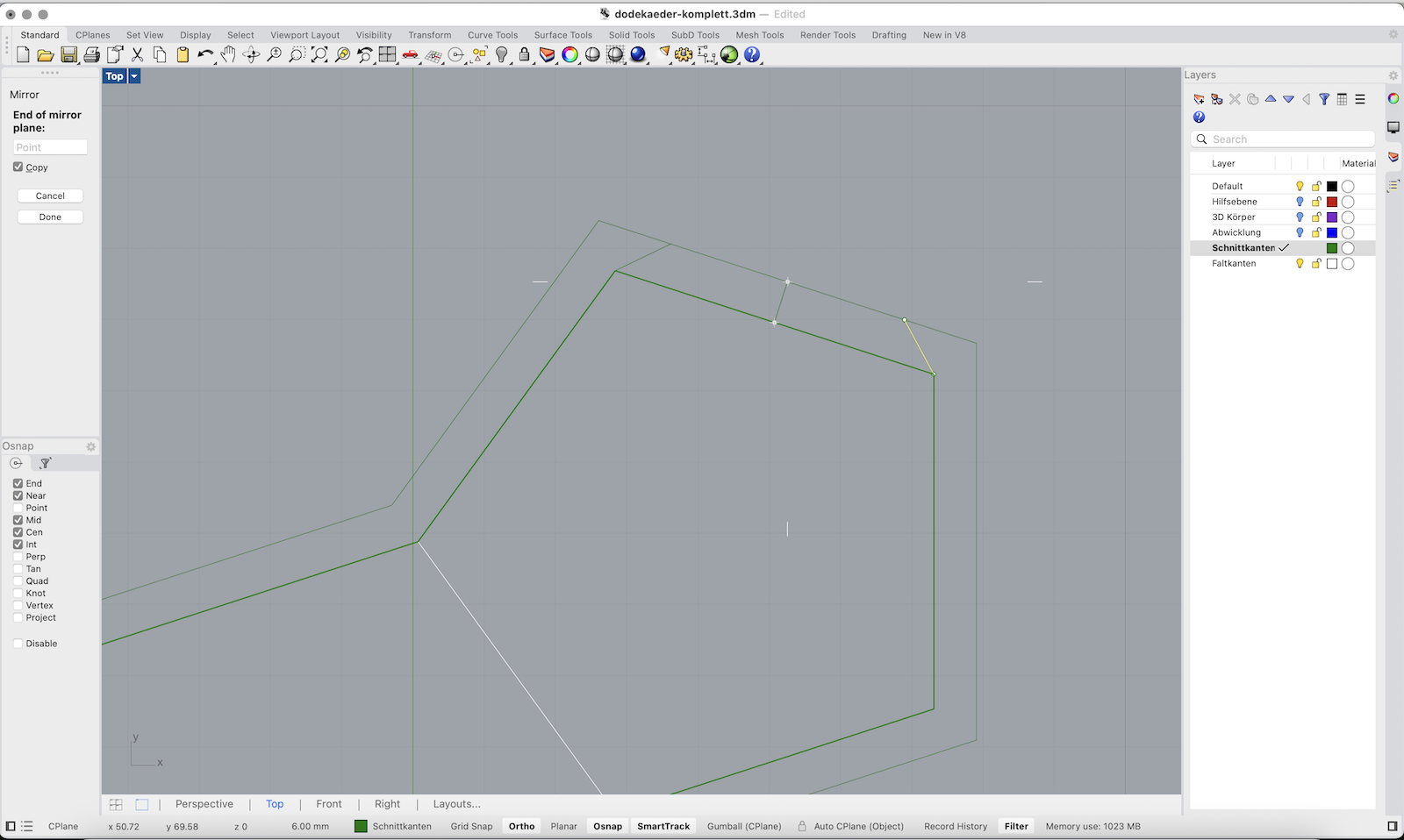
2. Use Mirror to copy the flap across the edge to the opposite side.
3. Repeat the process to place flaps wherever glue joints are needed.
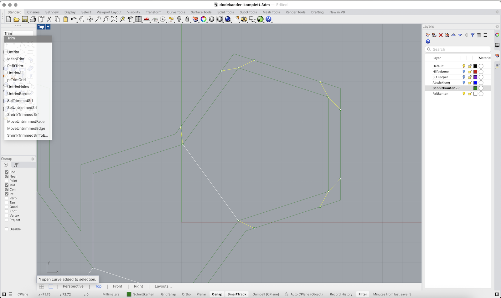
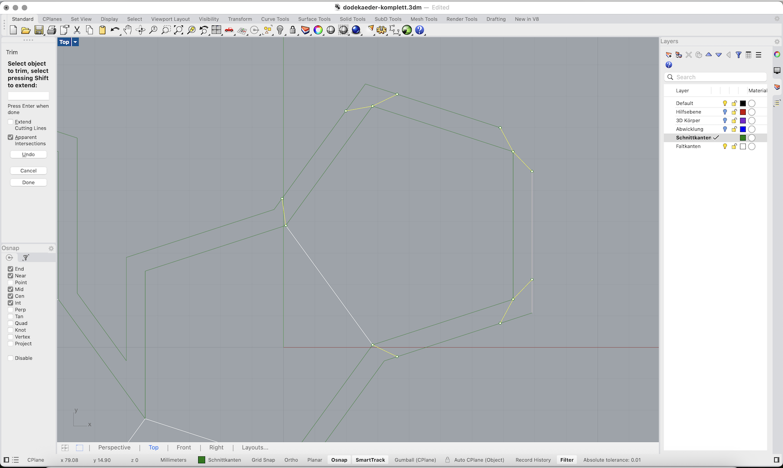
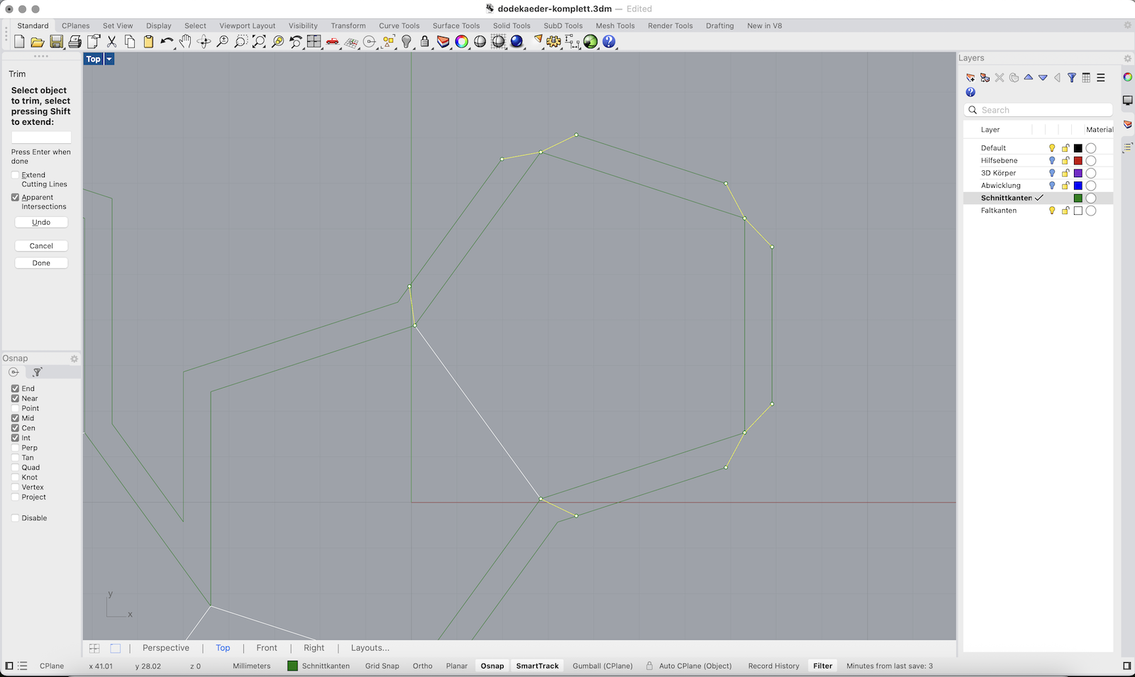
4. Use Trim to remove parts of the duplicated border where joints overlap or are not required.
5. Carefully check which sides need glue joints – not every edge needs one!
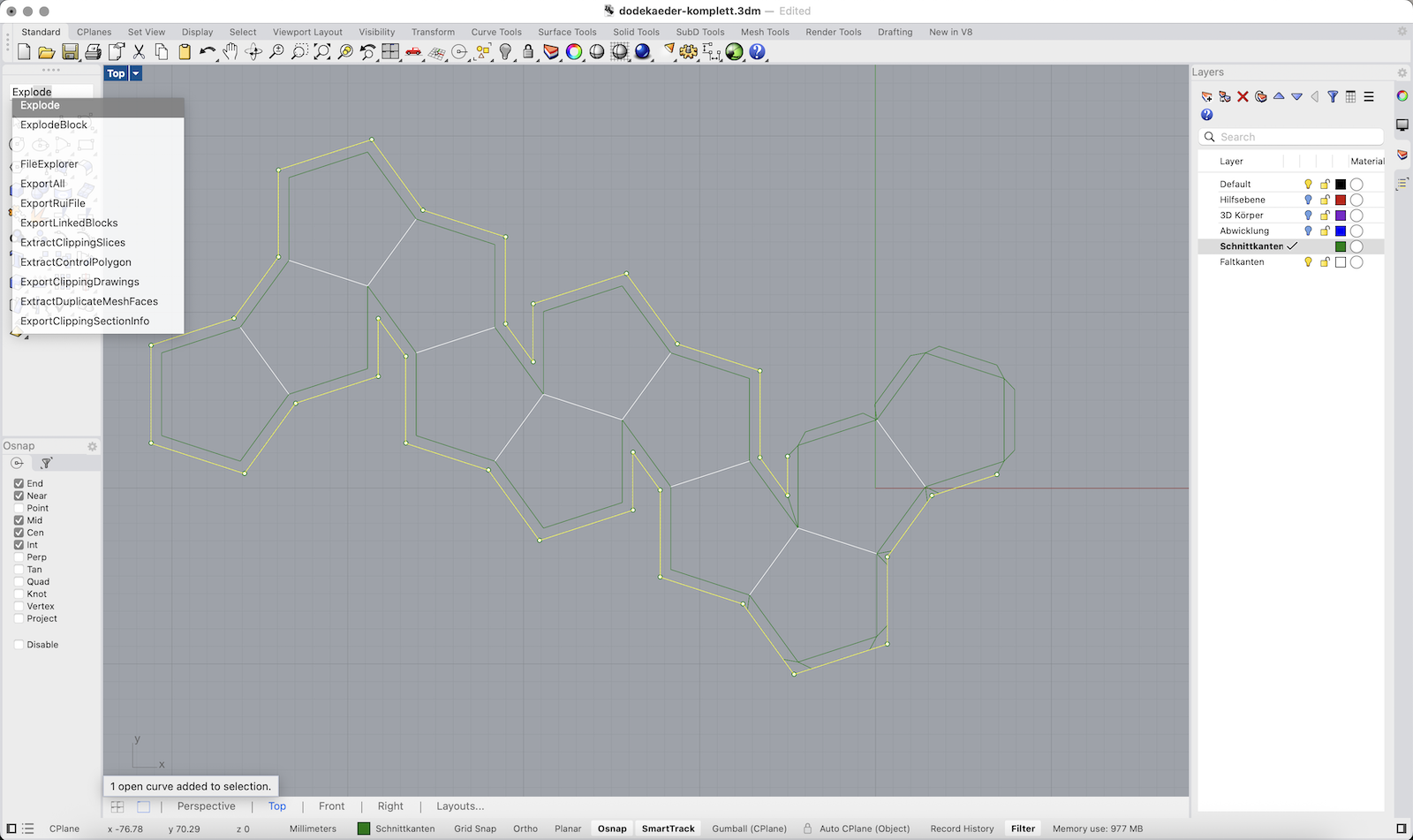
Final Cleanup
1. Select all lines, type Explode and press Enter to break all polylines into individual segments.
2. Make sure the Schnittkanten (cut lines) and Faltkanten (fold lines) are correct and organized in the right layers.
3. Double-check edge types: cut lines should form a closed outer boundary, fold lines only between surfaces.
4. Select all lines from the respective layers (cut and fold) and use Join again to reassemble them into closed polylines for laser cutting.
5. Export your geometries as dxf or dwg for laser cutting.