Overview
In this tutorial you will learn how to use lofts and surface manipulation tools to model a freeform vase ready for 3D printing.
Draw a circle
Start by drawing a circle. Either pick the command from the toolbar on the left side (third row from top, left) or by entering circle into the command line. Use. 0,0 as center of the circle and 60 mm as radius. Make sure to set your drawing dimensions to mm.

Draw free-form curves
Use control point curve (second row, right / curve) to draw a free-form curve. Use the circle as a guide for proportions. It is important to make a closed curve – meaning that where the curve ends must be at the same point as where it started. This can be done by entering ‘c’ when you’re done drawing.


Add as many different variations as you like around the first drawn circle. You may want to put different curves on separate layers so that they are easier to distinguish later. The layers tab is on the right side of the screen (Pie symbol). Change a shape’s layer by selecting the shape, right-clicking on the respective layer and choosing ‘change object layer’. It might also help to turn off the ‘Object Snap’ located at the bottom of the screen so the curves don’t snap to previously used control points.
Spread curves
Once all curves are drawn, select the curve which you want topmost and use move to move the curve along the Z axis. Use 0,0 as starting point and 0,0,80 as end point. This will set the vase height at 80mm. Make sure you’re in top or perspective view. Select the curve you want to have next and use the Gumball Tool in perspective view to move the curve along its Z axis. Gumball can be switched on and off at the bottom. Repeat this step for all remaining curves. There is a lot of trial and error with this type of design so you can experiment with different heights of how far apart from each curve you want them to be spaced.


Loft
Switch ‘Record History’ on, which can be found at the bottom next to ‘Gumball’.
Now the curves are joined into a surface using the loft command. When lofting curves it is very important to select the curves in order in which they are to be lofted. Select the bottom curve first and then select one by one each curve that is next in line above.
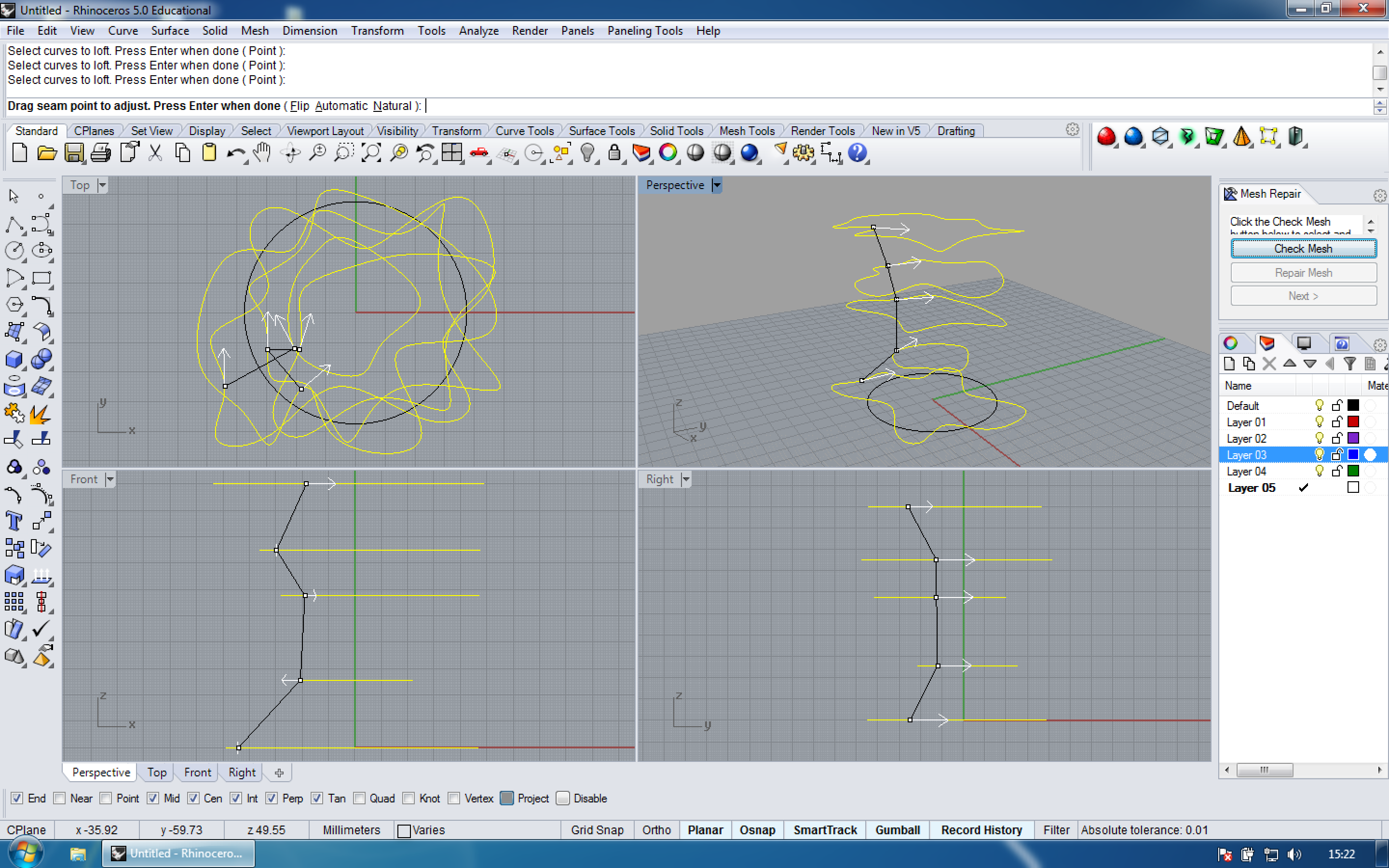

After the curves have all been selected and you pressed enter, there will be an option to ‘Drag Seam Point to Adjust’. Choose ‘Natural’. After pressing Enter, the Loft options box will appear. Set the viewing mode to ‘Rendered’ by clicking on the little triangle in the viewport window to see a preview of the lofted surface. Choose ‘Loose’ as the lofting style and press Enter.
Adjust surface and offset
Since ‘Record History’ stores the connection between a command’s input geometry and the result the surface can now be adjusted by simply modifying the input curves, like deleting control points, scaling or moving. This can again be done with the aid of ‘Gumball’.
Now choose ‘surface’ from the menu bar and then ‘offset surface’. Click on the surface to adjust the offset direction to the inside and enter 3 for distance. The wall thickness of the vase will be around 3mm.


Trim
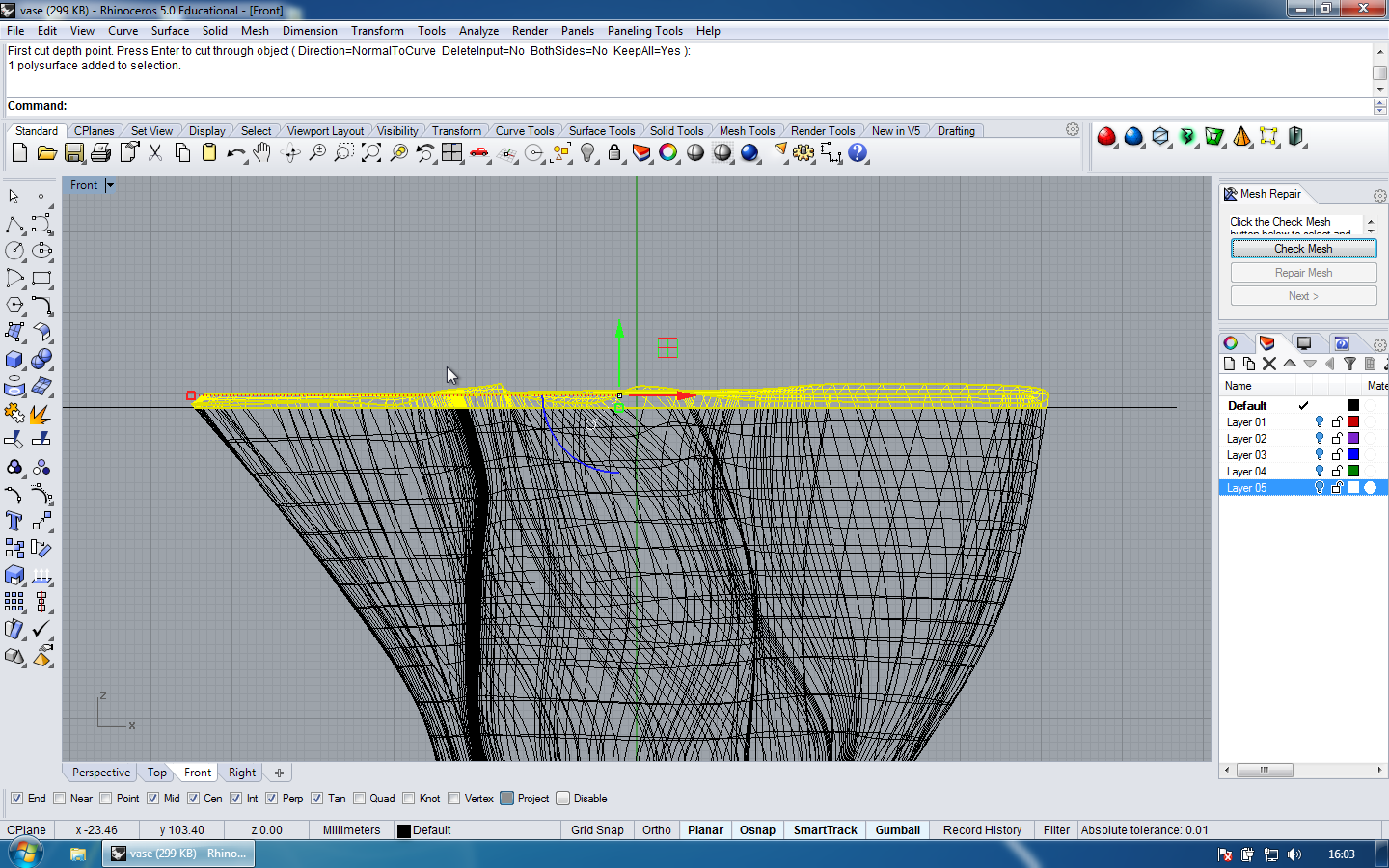
In front view draw a straight line across the geometry. Move the line towards the top of the shape, right before it gets a bit messy. In the command line type wirecut, select the shape and press Enter. Press Enter again. Choose the top part and delete it. Do the same for the bottom part of the shape.
Adding a base


Type move, select one of the bottom-most points of the shape and enter 0,0.
To create a Base for the Vase, draw a box (row 7, left / _box) with a height of 3mm.
To create the base so that it is just on the interior of the Vase, use Boolean Difference (menu bar – solid – difference). Select the box, press Enter and then select the shape and press Enter again. Delete the excess around the perimeter of the shape.
Select the newly created base and the shell of the vase and then Boolean Union (menu bar – solid – union) the two objects to create one solid, closed polysurface.
Type volume to check if the surface is ready for 3D printing. Volume is a tool within Rhino that shows the estimated volume of an object. For the volume to be calculated, the object has to be a solid, watertight model with ideally no non-manifold or naked edges, just as for 3D printing. The volume tool is also very useful because you can make an estimate on how much plastic material will be needed when 3D printed.

Export
Select the shape, go to File – Export Selected and then choose STL.
To accommodate different 3D printer technologies the Max Dist Edge to Srf values should be less than half a printer’s resolution. A setting of 0.01mm is good for a printer with a resolution of 0.03mm.
- Max angle: 20
- Max aspect ratio: 6.0
- Min edge length: 0.0001
- Max edge length: 6.0
- Max dist edge to srf: 0.001
- Initial grid quads 16
- Refine checked, all others unchecked
- File Type: Binary
