Overview
In this tutorial, you will learn how to use a top view image and a side view image of an object to model it. You will also be exploring new tools that will help you create organic shapes.
Preparation
To start with, begin a new model. In the Template File dialog box, select Small Objects – Millimeters. In the Top viewport, use the Line command to draw a reference line 50 millimetres long starting at 0,0,0.


Start the PictureFrame command (Surface toolbar>Planes flyout>PictureFrame, or type PictureFrame and Enter.) Find the image file DragonflyTop.jpg, and place the image in the Top viewport. Use the reference line to set the length of the picture frame image.

Use object snaps to Move the image from the midpoint of the left side (Mid) to the construction plane origin at 0,0,0.

Start the PictureFrame command. Find the image file DragonflySide.jpg and place the image in the Front viewport. Use the reference line to set the length of the picture frame image.

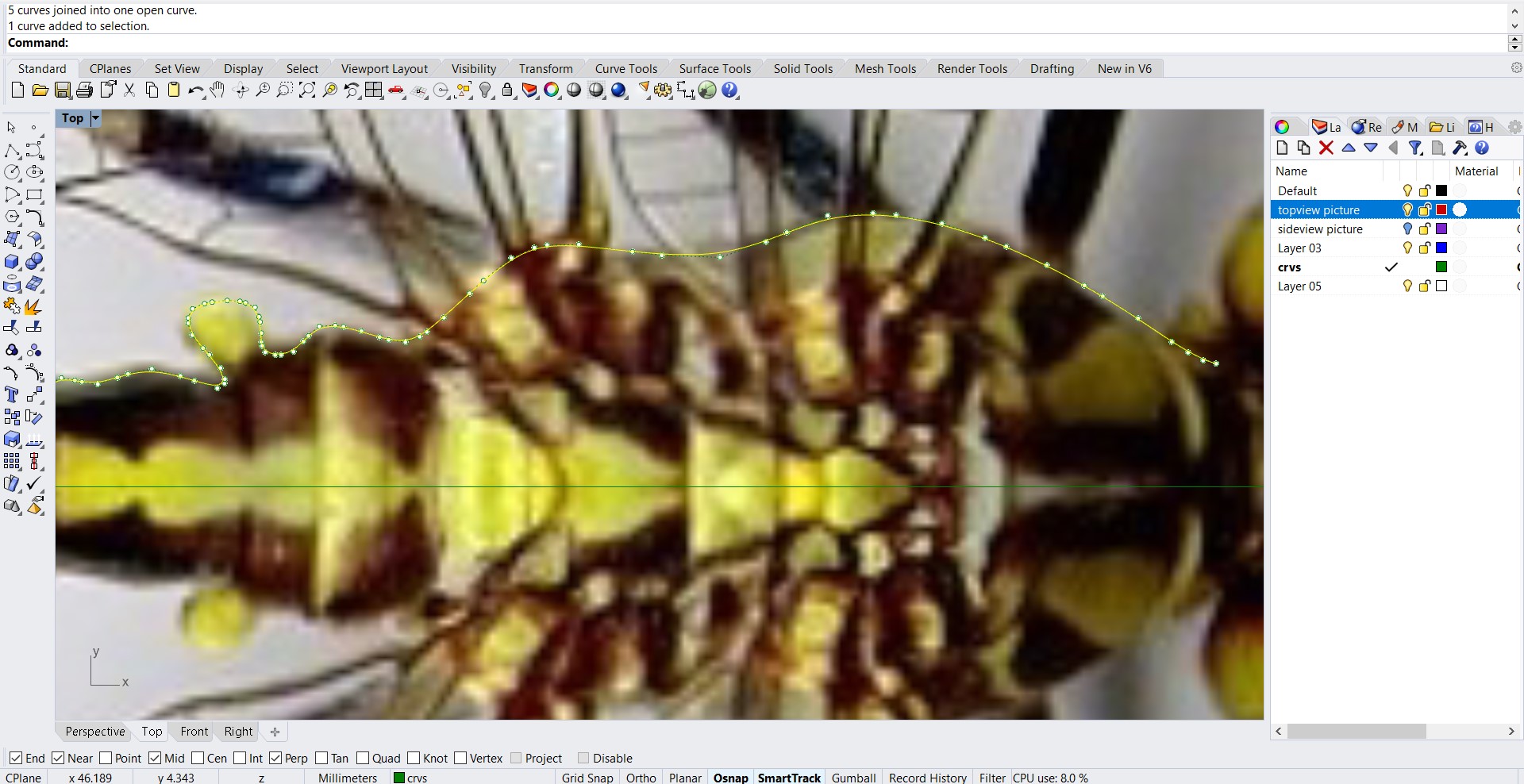
Now, we’re going to draw the outline curve. In the Top viewport, use the Curve command to draw an outline of the top half of the dragonfly body.
Use as many control points as you think are necessary for the detail. Draw only up to the neck. You will be creating the head another way.

In the Top viewport, use the Mirror command to copy the curve around the reference line.
The photograph shows that the dragonfly is not symmetrical about its center line. However, since your dragonfly will be stylized, it does not matter in this case. You can choose the level of accuracy you need.

Click on the lightbulb icon to make the side view image visible again.
In the Front viewport, use the Bend command to bend the curves down at the tail to match the bend in the body curve in that view.

In the Front viewport, use the Curve command to trace the body outline using two curves, one above the reference line and one below the reference line. Maximize the viewport and zoom in. Pick as many points as you need to create the curves. Use more points when rounding a corner and fewer points for a straight section.
Hide the picture frame objects and the reference line.

For the next command to work, you need to make sure that the outline curves you drew are accurate. There should be 4 lines that look like this:

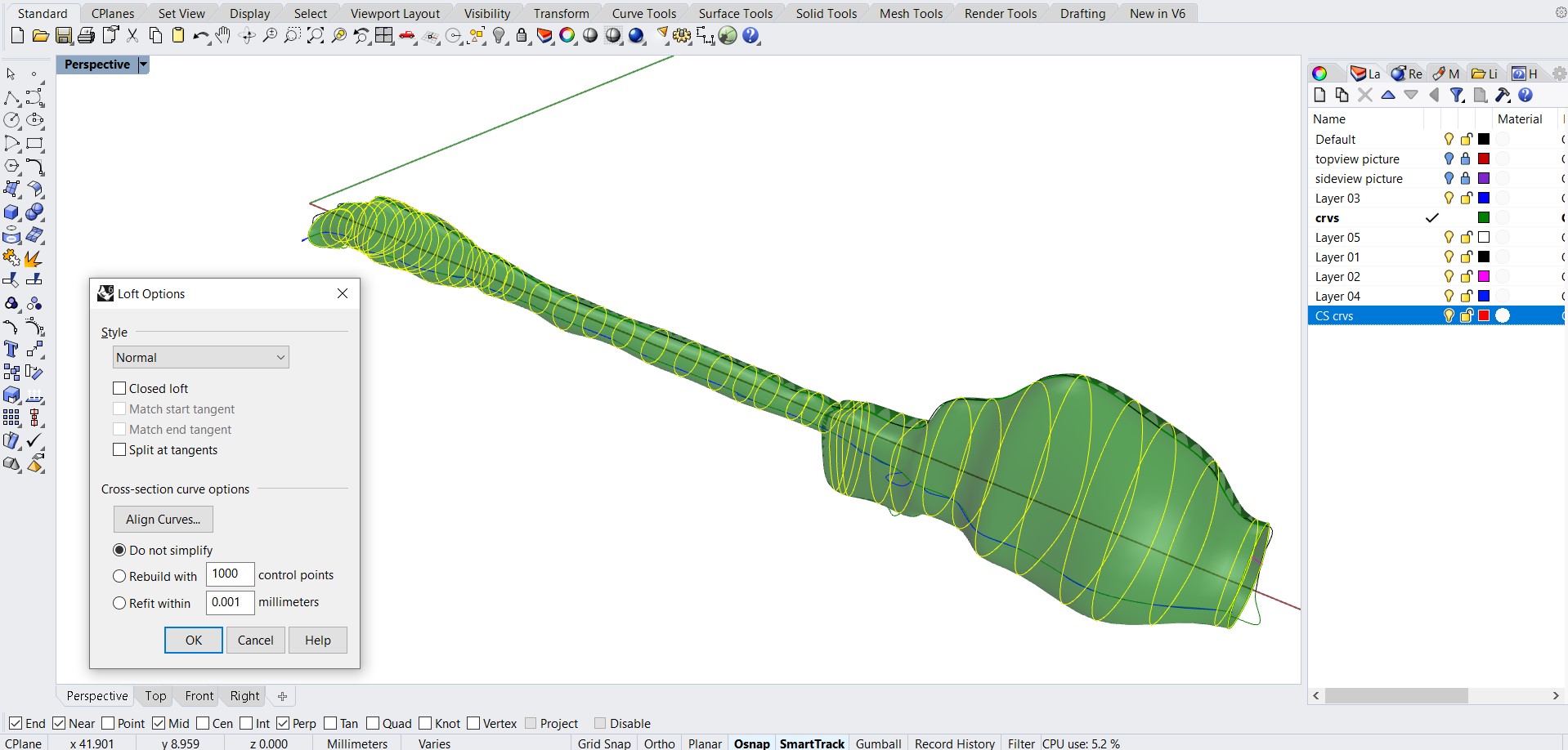
Use the CSec command to create cross-section profile curves through the top, bottom, and side curves.
Draw as many cross-section curves (in front view) as you need to maintain the detail. You will be able to see whether you have enough curves when you loft the surface in the next step. You have to select the curves in the right order. Select them in clock wise order. It should look like this when you’re done.
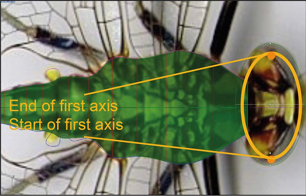
Use the Ellipsoid command with the Diameter option to start the ellipsoid in the Top viewport.

In the Front viewport, define the end of the second axis.

From the Right viewport, Project that rounded rectangle onto the body and delete the curves you don’t need. It is the one in the back.


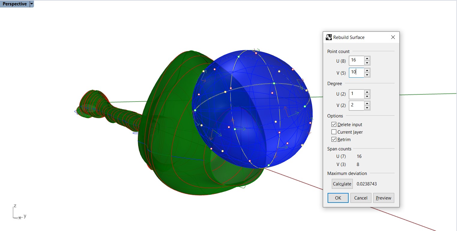
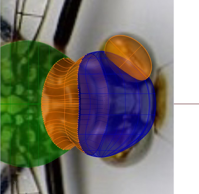
Use the Rebuild command to add more control points to the ellipsoid. Set the point count to 16 in the u-direction and 10 in the v-direction.

Use the PointsOn command to turn on control points for the ellipsoid

In the Top viewport, select and drag points on both sides of the ellipsoid toward the back to deform the head.


In the Front viewport, draw lines as illustrated, and use the Trim command to trim the head and body shapes with the lines


Use the BlendSrf command to make a blend surface between the head and body. Be sure the seams are aligned and the direction arrows point the same way.

Use the Ellipsoid command to draw the eye. Base the size and position on the images. Use the move and rotate tools to position the eyes on the right spot on the head.


Use the Mirror command to copy the eye to the other side.

Join the neck, and body.

If you look at the end of the tail, you’ll notice it’s open. Use the Cap command to make the body into a solid.

Use the Cylinder command to draw a solid cylinder so it cuts through the tail as illustrated.

Use the BooleanDifference command to cut the end out of the tail. The surface you want to subtract from is the body, the surface you want to subtract with is the cylinder.

Trace the wings. In the Top viewport, use the Curve command to trace the wings on one side of the dragonfly

Make the curves into thin solids with the ExtrudeCrv command. Set the distance to 0.3 points. Set the command-line option Solid=Yes to Yes.
Position the wings on the back with the Move command. Consult the side view image of the dragonfly. The front wing is slightly higher than the back wing.

Use the Mirror command to copy the wings to the other side.

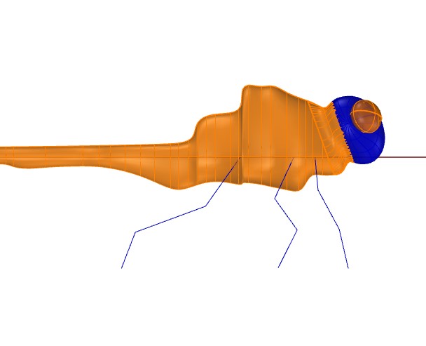


Use the Pipe command to draw the legs around the polylines. Set the start radius to 0.3 and the end radius to 0.15 and set the cap to “round”.

Use the Mirror command to copy the legs to the other side.
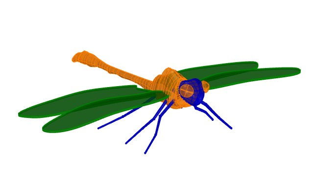
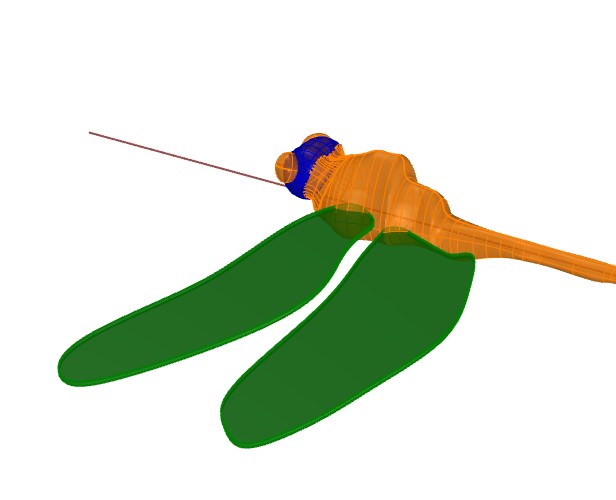
Show the wings, and your dragonfly is complete!